

SSW-MUMK
Mullion Mount Kit for SSW
Installation Guide
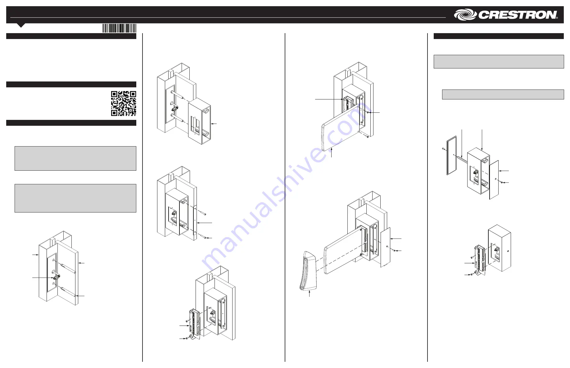
4. Place two of the included O-rings onto each of the toggle bolt rods, and then slide
the O-rings over the rods until they are positioned against the mullion.
5. Thread the USB cable from the center hole of the mullion into the mullion mount
and then out through the mount’s 1-gang front opening. Once the cable is
threaded, align the two slots inside the mullion mount with the toggle bolt rods, and
then slide the mount across the rods until it is positioned against the mullion.
Attaching the Mullion Mount to the Toggle Bolt Rods
8. Align the two holes on the acrylic face with the mounting posts on the SSW rear
assembly, and then push the acrylic face into the assembly so that the holes
completely engage the posts. The acrylic face stays in place once it is hung onto
the posts. Then, use the two 4-40 x 1/2" SEMS screws (included with the SSW)
and a Phillips screwdriver to secure the acrylic face to the posts. Remove the
plastic film from the acrylic face once it is secured.
Attaching the SSW Acrylic Face to the Rear Assembly
Surface Mounting
Use the following procedure to mount the touch screen onto a flat pane of glass or
similar smooth surface (such as granite, marble, plaster, or smooth stone and masonry)
using the included multisurface mounting parts.
NOTE:
Ensure that the mounting surface is free of debris and has been cleaned with a
glass cleaning product that does not leave a film before attaching the mount to the
surface.
1. Measure the size of the USB or Cresnet cable connector that is being run to the
SSW, and then drill an appropriately sized hole into the top, bottom, or side of the
mullion mount so that the connector can pass through. Then, route the appropriate
cable connector from the power source into the mullion mount and out through the
mount’s 1-gang front opening.
NOTE:
If running a cable to the side of the mullion mount, drill the hole for the
cable connector into the appropriate end cap.
2. Attach one of the end caps to the hex standoff using one of the 6-32 x 1/2" screws.
Then, place the end cap on one side of the mullion mount so that the standoff
enters the mount, and attach the other end cap to the other side of the standoff
using the other 6-32 x 1/2" screw.
Attaching the End Caps to the Mullion Mount
Description
The Crestron
®
SSW-MUMK provides a versatile mounting solution for the Crestron SSW
wall mounted room availability hallway sign. With the SSW-MUMK, the SSW can be
installed to the mullion of an interior glass wall, window, or partition. The SSW-MUMK
attaches to the left or the right inside surface of a vertical, hollow metallic mullion, and it
supports a concealed USB connection between the SSW and a Crestron TSW-560,
TSW-760, or TSW-1060 touch screen.
The SSW-MUMK also allows the SSW to be mounted directly onto glass, granite,
marble, plaster, smooth stone and masonry, or almost any other flat surface using the
included multisurface mounting parts.
Mullion Mounting
Use the following procedure to install the SSW-MUMK to a mullion:
1. Use the included cutout template to drill two 3/8" (10 mm) holes and one
5/8" (16 mm) center hole in the desired installation location on the mullion. The two
3/8" holes must be set 4-1/2" (114 mm) apart.
NOTE:
For a completely flush installation, locate the drilled holes
1-7/10" (43 mm) back from the face of the mullion.
NOTE:
Ensure that there is enough space between the drilled holes and the
touch screen to run the USB cable (included with the SSW) from the touch
screen up through the mullion to the SSW.
2. Once the holes are drilled, connect the USB A end of the SSW’s USB cable to the
USB port on the rear assembly of the touch screen, and then route the micro USB
end of the cable up through the mullion so that it exits the center hole.
NOTE:
If routing the USB A end of the cable from the mullion mount down
through the mullion to the touch screen, expand the center drilled hole to
3/4" (19 mm).
NOTE:
The SSW can also be connected to a Crestron control system or DMPS
device using any standard Cresnet
®
network cable. Route the cable from the
device and up through the mullion as described in the above step.
3. Insert the toggle bolt rods into the top and the bottom drilled holes in the mullion.
Rotate the rods to ensure that the toggles securely engage the mullion so that they
cannot be pulled out.
Inserting the Toggle Bolt Rods into the Mullion
Additional Resources
Visit the product page on the Crestron website (www.crestron.com)
for additional information and the latest firmware updates. Use a QR
reader application on your mobile device to scan the QR image.
Toggle bolt
rods (2)
Cable:
USB A to
micro USB
Mullion
Glass surface
Mullion mount
6. Secure the mullion mount to the toggle bolt rods with the metal locking plate. Use
the included Allen wrench and the two 8-32 x 5/8" screws to attach the locking
plate to the bolt rods.
Securing the Mullion Mount to the Toggle Bolt Rods
Screws (2):
8-32 x 5/8"
Metal locking plate
7. Connect the micro USB end of the USB cable to the micro USB port on the SSW’s
rear assembly, and then attach the assembly to the mullion mount’s 1-gang
opening using two 6-32 x 5/16" screws (included with the SSW) and a Phillips
screwdriver (not included).
Attaching the SSW Rear Assembly to the Mullion Mount
SSW
rear assembly
Screws (2):
6-32 x 5/16"
Screws (2):
4-40 x 1/2"
SEMS
SSW
acrylic face
9. Carefully slide the SSW’s bezel over the acrylic face and across the sign until the
bezel magnetically locks into place. Then, secure one of the end caps to the
mullion mount using one of the 6-32 x 1/2" screws and a Phillips screwdriver to
complete the installation.
Completing the Installation
SSW
bezel
Screw (2):
6-32 x 1/2"
End cap (2)
Screws (2):
6-32 x 1/2"
End caps (2)
Standoff
bar
Mullion
mount
3. Connect the cable connector to the SSW’s rear assembly, and then attach the
assembly to the mullion mount’s 1-gang opening using two 6-32 x 5/16" screws
(included with the SSW) and a Phillips screwdriver (not included).
Attaching the SSW Rear Assembly to the Mullion Mount
SSW
rear assembly
Screws (2):
6-32 x 5/16"
Mounting
posts (2)


