background image

INST.No.INE-559-P1

IR-BZ Series

COMPACT INFRARED

THERMOMETER

Model: IR-BZP

Always keep this instruction with the unit.

Please be sure to deliver these instructions
with the unit to the end user.

Summary of Contents for IR-BZ Series

Page 1: ...INST No INE 559 P1 IR BZ Series COMPACT INFRARED THERMOMETER Model IR BZP Always keep this instruction with the unit Please be sure to deliver these instructions with the unit to the end user ...

Page 2: ......

Page 3: ...eering mode 16 Details of engineering mode 17 9 1 Key lock set release 17 9 2 Selection of analog output 18 9 2 1 Setting of analog output minimum value 18 9 2 2 Setting of analog output maximum value 19 9 3 Analog dummy output 19 9 3 1 Analog dummy output1 19 9 3 2 Analog dummy output2 20 9 4 Selection of hold function 21 9 4 1 Selection of hold reset type 22 9 4 2 Setting of hold reset time 23 9...

Page 4: ...ales agent of CHINO Corporation NOTE 1 The descriptions of this manual are subject to change without notice 2 If a question has arisen or if an omission was found in this manual please contact your nearest CHINO s sales agent or your dealer 3 Copy right of this instruction manual belongs to CHINO Corporation All or part of this instruction manual shall not be released to the third party Thank you ...

Page 5: ...failures of the thermometer don t overhaul it by yourself and contact your sales agent of CHINO Corporation 3 Disposal When you discard this product please obey the regulation of each local government 4 Symbols in this instruction manual The symbols shown below are used depending on important degrees for using the thermometer safely and avoiding unexpected situations Important degree Symbols Conte...

Page 6: ... this thermometer may not only cause failure but also be dangerous to you Disassembling or modifying this thermometer is prohibited Caution May cause injury or physical damage Avoid using in the places where temperature changes widely humidity is high close to heavy electric circuit exist inductive interference is large static electricity exists or magnetic field and mechanical vibration and impac...

Page 7: ...ncy so it is excellent in environmental resistance 2 Model 2 1 Model IR BZ 1 2 3 E 4 1 Type P Separate 2 Element H Thermopile high speed 3 Distance and diameter G φ8 200 4 Cable length 1 1 5m 3 3m 8 8m 1 F 15m 1 1 CE marking non approved 2 Conformity requirements Use of power supply for IR BZ exclusive use and the connecting cable up to 30m indoor use 2 2 Configuration Detector Main unit EN61326 1...

Page 8: ...mp Lights when self diagnostic alarm activates Also it will light when the contact output is set as ALM high or low alarm and alarm activates 4 Cable gland Detector side Cable inlet for Detector not removal 5 Cable gland Power supply and signal line side Cable inlet for power supply and signal line 6 Hole for installation φ4 5 two holes for fixing the unit 1 Digital display 2 Function key 4 Cable ...

Page 9: ...displayed depending on the setting At operating mode and engineering mode parameter name is displayed in 4 digit LCD At emissivity setting emissivity set value and at transmittance setting transmittance set value is displayed Name Marker Function Indication 4 Main marker Tb Not used Tb CONT CONT MEM MEM PEAK PEAK 5 Status marker AL It is lit at low alarm activation AL AH It is lit at high alarm ac...

Page 10: ...or 10 C or lower Ambient temperature changes widely or humid is high Close to high frequency line or power line Mechanical vibration and impact exist Flammable or explosive gases exist Unit mm 12 80 17 72 70 19 5 30 Cable gland for power supply and signal lines Installation hole 2 φ4 5 Cable gland for Detector not removal 10 Compatible cable diameter φ6 5 to φ8 62 Unit mm 28 10 M12 P1 φ14 Cable 1 ...

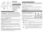
Page 11: ...INST No INE 559 P1 5 4 3 Measuring Diameter and Measuring Distance Unit mm φ16 φ8 400 200 ...

Page 12: ...24 or more 9 5V or higher 100m or shorter 0 3mm2 AWG22 or more 9 5V or higher 200m or shorter 0 3mm2 AWG22 or more 11V or higher 1 Loosen four of M3 screws of Main unit and remove a lid 2 Set a cable to the cable gland and connect to a terminal block Press a button on the terminal block while inserting the wire and release the button after the insertion To prevent an electric shock turn OFF the po...

Page 13: ...connect either signal to be used 5 2 2 Connection of power supply terminal 5 2 3 Connection of grounding terminal 5 2 4 Connection to receiving devices Analog output is non isolated 0 or 4 to 20mA DC thermocouple EMF equivalent voltage Connect output terminal and receiving devices to each other Contact output is open collector output Use connecting external device rated 30V 50mA or lower Use 8 to ...

Page 14: ...ow or high Displaying Lock on sub display if key lock set is selected 1 Main display 7 segment LCD 4 digit Measured value and set value setting item selection value selection item are displayed 2 Sub display 7 segment LCD 4 digit At measurement selected item by SEL key and at setting setting item is displayed 3 Sub marker ε emissivity r transmittance 4 Status marker AL low alarm AH high alarm 5 Me...

Page 15: ...perating mode and emissivity transmittance signal modulation and alarm etc selection setting become enabled Refer to Details of operating mode on 8 Operating mode Engineering mode By long pressing about 2 sec on the SEL key it shift to setting screen at the engineering mode and key lock analog output scaling analog dummy output hold function contact output sub display selection and communication s...

Page 16: ...neering mode Key lock Set Release Analog output selection Analog output lower limit Analog output higher limit Analog dummy output1 Analog dummy output2 SEL SEL SEL SEL SEL Select hold function Hold reset types Hold reset time SEL SEL SEL SEL Time constant digit after decimal point SEL Contact input selection SEL SEL Sub display selection SEL Device address SEL Communication speed SEL Long press o...

Page 17: ...hown on the right It returns to the measurement mode by long pressing about 2 sec on SEL key It also returns to the measurement mode if no key operation is performed for 1 minute Operating mode diagram Operating mode Emissivity setting Transmittance setting Signal modulation Modulation time constant Alarm types Alarm temperature Measurement mode SEL SEL SEL SEL SEL SEL SEL SEL Signal modulation dE...

Page 18: ...n on the right figure on sub marker Present temperature is displayed on the main display 2 Press key or key and change setting numeric value for transmittance Setting is completed by changing the numeric value 3 It shifts to the next screen by pressing the SEL key Setting range is 1 999 to 0 100 Default setting is 1 000 Setting range is 1 999 to 0 100 Default setting is 1 000 It returns to the mea...

Page 19: ...of time constant set at 8 4 1 Setting of modulation time constant When signal value fluctuates it displays in smooth form PEAK If temperature is rising it displays the value based on original signal If temperature is dropping the value is displayed based on attenuation rate setting Refer to 8 4 2 Attenuation Incarease rate setting VALL VALL is the opposite process of PEAK If temperature is droppin...

Page 20: ...r key and change numeric value of modulation time constant Setting is completed by changing the numeric value 3 It shifts to the next screen by pressing the SEL key 8 4 2 Selection of attenuation Increase rate This is valid only if PEAk or VALL is selected for signal modulation PEAk or VALL can be traced Signal attenuation rate after the peak or signal increase rate after valley is selected 1 Pres...

Page 21: ...tion is completed by changing the display 3 It shifts to the next screen by pressing the SEL key Alarm types Hi High alarm If an indication value exceeds the alarm point open collector of the contact output turns ON Lo Low alarm If an indication value fall below the alarm point open collector of the contact output turns ON no no alarm 8 5 2 Temperature setting of alarm 1 After registering Alarm at...

Page 22: ... performed for 1 minute Engineering mode diagram Measurement mode Engineering mode Key lock set release Analog output selection Analog output lower limit Analog output higher limit Analog dummy output1 Analog dummy output2 SEL SEL SEL SEL SEL Select hold function Hold reset types Hold reset time SEL SEL SEL SEL Time constant digit after decimal point SEL Contact input selection SEL SEL Sub display...

Page 23: ...hanged Except deactivate the key lock setting 1 Press the SEL from engineering mode screen to display LCK S shown on the right figure on sub display 2 Press key or key and select key lock set YES or release NO Set release is completed by changing the display 3 It shifts to the next screen by pressing the SEL key It returns to the measurement mode if no key operation is performed for 1 min Key lock...

Page 24: ...shifts to the next screen by pressing the SEL key Default setting is 4 20 mA Outputtable max temperature range is from 50 to 1100 C and upper limit depends on the unit from 1030 to 1100 C 4 20 CONT PEAK AL AH Tb MEM tCJ CONT PEAK AL AH Tb MEM tCK CONT PEAK AL AH Tb MEM tCr CONT PEAK AL AH Tb MEM tCrS CONT PEAK AL AH Tb MEM Sub display Main display 0 20 CONT PEAK AL AH Tb MEM Setting range is 50 to...

Page 25: ...ion 1 Press the SEL key couple of times from engineering mode screen to display Out1 shown on the right figure on sub display 2 Press key or key and change set value of analog dummy output1 Setting is completed by changing the numeric value 3 It shifts to the next screen by pressing the SEL key Setting range is 50 to 3500 C However outputtable upper limit depends on the unit from 1030 to 1100 C De...

Page 26: ...tput2 Setting is completed by changing the numeric value 3 It shifts to the next screen by pressing the SEL key Setting range is 50 to 3500 C Output EMF corresponding to set temperature abd selected thermocouple Output range is as below tCJ 50 to 1200 C tCk 50 to 1370 C tCr 50 to 1760 C tCS 50 to 1760 C However outputtable max temperature range is from 50 to 1100 C and upper limit depends on the u...

Page 27: ...ed by changing 3 It shifts to the next screen by pressing the SEL key Hold function types no no hold mode PEAK peak hold VALL valley hold opposite process of PEAk SAMP sample hold Peak hold CONT PEAK AL AH Tb MEM Sample hold is hold at startup of external contact input 55ms or more is necessary for contact input start up detecting pulse width Temperature display and analog output of sample hold mo...

Page 28: ... Peak hold external reset External contact input 9 4 1 Selection of hold reset type Register this function if peak or valley hold is selected at previous section 1 After register of PEAK or VALL at the previous section press the SEL key to display H rSt shown on the right figure on sub display 2 Press key or key and change hold reset types Selection is completed by changing 3 It shifts to the next...

Page 29: ...ent unit selection This mode is for the selection of the measurement unit for measured temperature 1 Press the SEL key couple of times from engineering mode screen to display unit shown on the right figure on sub display 2 Press key or key select C or F Selection is completed by changing 3 It shifts to the next screen by pressing the SEL key Setting range is 0 0 to 99 9 sec Default setting is 0 0 ...

Page 30: ...by pressing the SEL key Setting range is 1 to 2 digit after the decimal point Default setting is 1 digit after the decimal point Change set value of modulation time constant at changing time constant digit after decimal point Changing digit after the decimal point 1 2 If set value of modulation time constant is 10 0 or more change to 9 99 Changing digit after the decimal point 2 1 Round down 2 dig...

Page 31: ...ion is completed by changing 3 It shifts to the next screen by pressing the SEL key Default setting is no no contact input For each operation details refer 9 4 1 Selection of hold reset type for hold rest and 9 4 Selection of hold function for sample hold Contact input types no no contact input H rSt hold reset SAMP sample hold No contact input CONT PEAK AL AH Tb MEM Sub display Main display Hold ...

Page 32: ...s from engineering mode screen to display Sub shown on the right figure on sub display 2 Press key or key and change sub display types Selection is completed by changing 3 It shifts to the next screen by pressing the SEL key CONT PEAK AL AH Tb MEM No contact output Sub display Main display Default setting is ALM high low alarm Contact output types No no contact output ALM high low alarm shorten wh...

Page 33: ...imes from engineering mode screen to display SPd shown on the right figure on sub display 2 Press key or key and change communication speed types Setting is completed by changing 3 It returns to the measurement screen by pressing the SEL key Device address CONT PEAK AL AH Tb MEM Sub display Main display Setting range is 1 to 32 Default setting is 1 Default setting is 9 6 9600bps Communication spee...

Page 34: ...tput Note Abnormal Detector temperature Check if the Detector is overheated or overcooled Abnormal main unit temperature Check if the main unit is overheated or overcooled E2 PROM abnormal Impossible to write or read to or from E2 PROM Off site repair return to the factory Abnormal input signal Check if the thermometer is used in the temperature exceeding measuring temperature range on a large sca...

Page 35: ...items Countermeasures 1 Check that temperature of measuring surface is not exceeding thermometer s measuring range Use a thermometer corresponding to the measuring range 2 Check that setting of emissivity is not too low Refer to 8 1 Emissivity setting and set correct emissivity 11 2 3 Indication fluctuates Inspection items Countermeasures 1 Check that power supply voltage is in normal range Supply...

Page 36: ...ntact output Self diagnostic error alarm high alarm low alarm select 1 point Output type open collector 1 point 30V DC 50mA Contact input Non voltage contact point Sample hold or peak valley hold reset Communication interface RS 485 transmit measured data transmitted and receive parameters Operation key Operating mode emissivity transmittance signal modulation and alarm etc setting Engineering mod...

Page 37: ...ting r 1 999 to 0 100 1 000 8 2 Signal modulation mode selection Modu dELy PEAk VALL dELy 8 3 Modulation degree setting 1 tAu dEC 0 0 to 99 9 sec 0 2 5 10 C sec 0 0 sec 0 C sec 8 4 1 8 4 2 Alarm type selection AL1M Hi high alarm Lo low alarm no no alarm Hi 8 5 1 Alarm temperature setting ALM1 50 to 3500 C 1000 C 8 5 2 1 Parameter of modulation degree selection depends on the setting of signal modu...

Page 38: ...on HoLd no no hold mode PEAk peak hold VALL valley hold SAMP sample hold no 9 4 Hold reset type H rSt no no reset in internal reset Et external reset no 9 4 1 Hold reset time r tiM 0 0 to 99 9sec 0 0 sec 9 4 2 Setting of time constant digit after decimal point tAu d After the decimal point 1 to 2 digit s After the decimal point 1 digit 9 5 Contact input selection din no no contact input H rSt peak...

Page 39: ... for 2 sec 2 init in main display blinks 3 Press and hold for 3sec 4 Blinking init lights up and initialization is completed If keys are released while init is blinking initialization stops All settings are returned to default setting Take a note of necessary set value before the initialization Caution ...

Page 40: ... BZP Main unit 80 72 12 17 70 62 30 14 16 19 5 10 Cable gland Detector cable inlet Cable gland Power supply signal cable inlet Compatible cable dia φ6 5 to φ8 Mounting hole 2 φ4 5 17 34 4 2 M3 4DP Mounting screw for DIN rail mounting base IR ZBDP Unit mm ...

Page 41: ...UT A TC White Green A GND Brown OUT HT White Brown COM Yellow DI White Yellow DO Gray FG Marker Communication RS 485 Power supply 8 36V DC Analog out1 0 20mA 4 20mA or T C Analog out2 Detector temp Contact input output Grounding 15 2 IR BZP Detector 15 3 Connecting cable IR ZBP Unit mm 28 10 M12 P1 Detector cable 1 5 3 8 or 15m OD φ3 3 Heat resistant 100 002 2m 005 5m ...

Page 42: ...4 Mounting bracket for Detector IR ZBMP 15 5 DIN rail mounting base for Main unit IR ZBDP Unit mm 90 16 22 φ3 5 22 31 20 44 35 2 φ4 6 M3 countersunk not used 34 4 17 6 23 3 23 3 55 5 3 5 8 5 Unit mm Mounting hole for Main unit ...

Page 43: ......

Page 44: ...UMANO CHO ITABASHI KU TOKYO 173 8632 Telephone 81 3 3956 2171 Facsimile 81 3 3956 0915 Web site http www chino co jp INE 559 P0 Feb 2017 IR BZSeries COMPACT INFRARED THERMOMETER Model IR BZP Printed in Japan ...

Reviews: