Installation and Technical Information
BEGA
In the interest of product improvement, BEGA reserves the right to make technical changes without notice.
Replacement Parts
Accessories
Please refer to the appropriate
accessory installation sheet for
further instruction when applicable.
BEGA
1000 Bega Way, Carpinteria, CA 93013 (805)684-0533 Fax (805)566-9474 www.bega-us.com © Copyright BEGA-US 2018
Pole top - indirect
77 210
Tools Required:
5mm hex key
6mm hex key
8mm hex key
Adjustable wrench
Protection Class:
IP65
Weight:
50.0 lbs.
Dimensions
A:
39-3/8 “
B:
22-5/8 “
Relamping/Maintenance
NO relamping required.
Lamp:
55.3W LED
77 210
10/9/2018
Page 1 of 2
Description
Lens
Lens gasket
Driver (120-277V)
LED Module (3000K)
LED Module (4000K)
Part No
140878
830647
75976
LED-0721/830
LED-0721/840
Notice to Installer for 77 210:
1. Do not open luminaire.
2. For pole top applications only.
3. Slip fits 3” O.D. pole top or tenon.
4. Luminaire requires at least 3-1/2” of straight diameter pole or tenon.
77 210 assembly:
1. Loosen the (2) 8mm hex screws at the top of the support rods and remove
screws and fixing plates.
2. Attach the reflector disk to the support rods by positioning the joint shells over the
joint bearings. Make sure the drip edges are oriented downwards.
3. Replace the fixing plates and screws.
4. Tilt the reflector to the desired orientation (0-30 degrees). Consult factory for
non-adjustability option.
5. Tighten the (2) 8mm screws to secure in place.
77 210 - installation:
1. Carefully hinge down pole, exposing bottom of pole.
2. Route the luminaire wiring through to the pole top base and slip luminaire over
the top of the pole.
3. Tighten the (8) 5mm set screws evenly to secure to pole.
4. Make wiring connections from luminaire wires to gear tray wires by attaching the
(2) quick-connect terminals securely.
NOTE: ONLY attach luminaire wires to specifi ed gear tray wires.
5. Place the gear tray in the base of the pole and tighten the 5/16” hex bolt to wedge
inside pole and secure.
6. Make supply wiring connections to gear tray wires:
MAIN VOLTAGE SUPPLY WIRE TO BLACK DRIVER WIRE
NEUTRAL (COMMON) SUPPLY WIRE TO WHITE DRIVER WIRE
GREEN GROUND WIRE TO GREEN DRIVER WIRE
Dimming (if applicable):
DIMMING CONTROL WIRE (+) TO POSITIVE LUMINAIRE DIM
CONTROL WIRE
DIMMING CONTROL WIRE (-) TO NEGATIVE LUMINAIRE DIM
CONTROL WIRE
7. Replace pole to upright position and secure by tightening (3) base bolts.
IMPORTANT: PLEASE NOTE THE WEIGHT OF LUMINAIRE HEAD ON
POLE AND TAKE CAUTION ACCORDINGLY DURING POLE TILT.
indirect cutoff optics
/
Pole top w
suitable for wet locations.
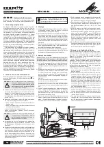
6mm and 8mm Hex Keys
Adjustable Wrench
BEGA
Installation and Technical Information
Tools Required:
Dimensions
A:
B:
39-3/8 "
24-1/4 "
UL listed,
IP 65
50.0 lbs
Protection Class:
Weight:
8309MH
Notice to Installer for 8309MH:
Luminaire slip fits a 3" O.D. pole top.
1.
Luminaire requires ballast mounted in minimum 5" butt hinge base pole. NOTE: Lower pole
before installing luminaire and ballast tray.
2.
8309MH assembly:
Loosen (2) M8 socket head screws and remove cover ring and glass with gasket.
1.
Insert lamp.
2.
Replace glass with gasket. Make sure the grooved side of the glass fits the underside of the
cover ring. Otherwise, flip the glass. And make sure the gasket is seated flush to ensure
proper seal.
3.
Tighten the (2) M8 screws evenly.
4.
Loosen the (2) M10 socket head screws at the top of the support rods and remove screws
and fixing plates.
5.
Attach the reflector disk to the support rods by positioning the joint shells over the joint
bearings. Make sure the drip edges are oriented downwards.
6.
Replace the fixing plates and screws.
7.
Tilt the reflector to the desired orientation (0-30º). Consult factory for non-adjustability
option.
8.
Tighten the (2) M10 screws to secure in place.
9.
8309MH installation:
Route the luminaire wiring through to the pole base and slip the pole top base over the top
of the pole.
1.
Tighten the (8) M10 set screws evenly to secure to pole.
2.
Make wiring connections from luminaire wires to ballast tray wires:
BLACK LUMINAIRE WIRE TO BLACK MARKED "SOCKET" WIRE
WHITE LUMINAIRE WIRE TO WHITE MARKED "SOCKET" WIRE
GREEN LUMINAIRE WIRE TO GREEN GROUND WIRE
3.
Place the ballast tray in the base of the pole and tighten the 5/16" hex bolt to secure.
4.
Make supply wiring connections to ballast tray wires:
MAIN VOLTAGE SUPPLY WIRE TO BLACK BALLAST WIRE
NEUTRAL (COMMON) SUPPLY WIRE TO WHITE BALLAST WIRE
GREEN GROUND WIRE TO GREEN BALLAST WIRE
5.
Relamping/Maintenance
Accessories
Replacement Parts
Lamp:
Philips :
Osram/Sylvania :
GE :
MC150T6/U/G12
CMH150/T/U/G12
CDM150/T6
Disassemble cover ring and glass. Clean dirt and
deposits from the luminaire and glass using only
solvent-free cleaners. Relamp and replace gasket if
damaged. Reassemble cover ring and glass.
Description
Part No
Diffuser
Gasket
Lampholder
Ballast (120V/208V/240V/277V)
140273
830647
74121
75146
(1) 150W T6 G12 MH
Please refer to the appropriate
accessory installation sheet for
further instruction when applicable.
In the interest of product improvement, BEGA reserves the right to make technical changes without notice.
BEGA
1000 Bega Way, Carpinteria, CA 93013 (805)684-0533 Fax (805)566-9474 www.bega-us.com © Copyright BEGA/US 2004
2/2/2006
8309MH