Avital 2200, Installation Manual
The Seal One 2200 User Manual is your ultimate guide to effectively operating and maintaining this cutting-edge product. Easily downloadable for free from manualshive.com, this comprehensive manual equips you with step-by-step instructions and valuable insights to maximize your experience with the Seal One 2200.
Share
Download


Reviews:
No comments
Related manuals for 2200
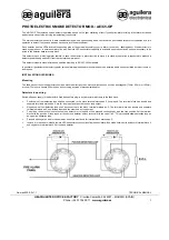
AE/C5-OP
Brand: aguilera electronica Pages: 2

ASTRA 777 Mobile
Brand: Scytek electronic Pages: 28

AutoCommand 20095
Brand: Directed Electronics Pages: 57

RF-51-eDp
Brand: Excalibur Pages: 20

560XV
Brand: Directed Electronics Pages: 55

CO03D
Brand: x-sense Pages: 29

Wake 'n' Shake Voyager
Brand: Geemarc Pages: 2

DC-9101 IS
Brand: GST Pages: 2

Prestige APS-920
Brand: Audiovox Pages: 12

Platinum+ APS 687C
Brand: Audiovox Pages: 12

SMOKE & CO URZ0413
Brand: Cabletech Pages: 44

Moondance Glow M402SR
Brand: Altec Lansing Pages: 28

Fortress FS-10
Brand: CrimeStopper Pages: 16

CS-790MX
Brand: CrimeStopper Pages: 15

CS-9228MX
Brand: CrimeStopper Pages: 23

75903
Brand: Equity Pages: 2

70902
Brand: Equity Pages: 2

70901
Brand: Equity Pages: 2


