30308679
Issue 1.04
Features
Sensitivities programmable.
Strong
environmental
adaptability
due
to
drift
compensation.
Integrated algorithm for analyzing fire, improving the
sensitivity highly.
Self-diagnostic.
Reed switch testing.
Removable innovative sensing chamber, easy for
maintenance.
Reporting dirt fault for contaminated chamber.
Fire LED allows 360
°
viewing.
3-level sensitivities and fixed temperature or rate of rise
programmable.
Description
DC-9101 (IS) Intrinsically Safe Conventional Combination
Heat
Photoelectric
Smoke
Detector
(the
detector),
non-addressable, is a kind of combination detector consisting
of smoke sensing parts and semi-conductor heat sensing
parts in technological structure and circuit structure. It’s
applicable to zone 1 and zone 2 of areas with explosion-proof
requirement in petroleum and chemical industries. It can
match with fire alarm control panel, I-9332 Interface,
explosion-proof detector and end-of-line resistor produced by
GST to conduct the processing of detector signals. The
detector has the advantages of both conventional
photoelectric detector and rate of rise and fixed temperature
heat detector. Just because of the combination of smoke
detector and heat detector, it overcomes the non-sensitivity
to dark smoke particles of ordinary scattering photoelectric
detectors. It can also pick up fire with obvious rise of
temperature such as alcohol flame, thus extending the
application range.
Connection and Cabling
Fig.1 shows the detector bottom and Fig. 2
the base.
A
C
B
100mm
A
Fig. 1 Fig. 2
There are four terminals with numbers on the base.
1: Detection zone positive IN
2: Detection zone positive OUT
3: Detection zone negative IN and OUT
4: No connection.
Recommended Cabling
1.0mm
2
or above fire cable. The capacitance distributed
among cables should not be over 0.083
μF, and the
inductance distributed should not be over 4.1mH. Laid out
through metal conduit or flame-retardant conduit, subject to
local codes.
Installation
Fix the base with two tapping screws, and then align mark A
on the detector bottom with B on the base, rotate the detector
to align mark A with mark C (Refer to Fig. 1 and 2 for the
position of the marks), the detector will be fitted to the base.
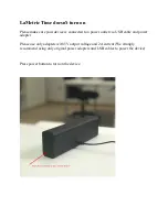
Fig.3 shows the mounting of the detector.
Fig. 3
Application
Warning: The alarm current depends on the current limit
of the control panel. 24VDC cannot power the detector
directly. Otherwise the detector will be blown up for lack
of current limit resistor.
The sensitivity level 1 is defaulted, which can be modified by
P-9910B programmer. Refer to P-9910B Hand Held
Programmer Installation and Operation Manual for details.
In power-on state, input unlocking password and press
Clear
to unlock. Press
Function
, then number
“3”, the screen shows
“-” at the last digit.
Note: Programming should be done in safety zones
because
handheld
programmers
belong
to
non-intrinsically safety devices.
Input corresponding sensitivity or parameter and press
Program
, the screen will show a “P”, the corresponding
sensitivity or parameter is programmed. Press
Clear
to clear
the "P". Input locking password and press
Clear
to return.
Rate of rise and level 1 is defaulted.
Parameters set using programmer
Input Number
Smoke Sensitivity
Heat Sensitive
1
Level 1
Rate of rise
2
Level 2
Rate of rise
3
Level 3
Rate of rise
11
Level 1
Fixed temperature
12
Level 2
Fixed temperature
13
Level 3
Fixed temperature
If the detector connects with fire alarm control panel, I-9332
interface and other exposition proof products in series, a
4.7k
Ω
end-of-line resistor should be connected to the end of
loop. System connection is shown in Fig. 4. Note the polarity
of power line.
Fig. 4
The interface is integrated with a safety barrier, which shall
be installed in safe area. The total number of explosion-proof
devices connected in the system shall not be over 10.
Safety Barrier Parameters
:
Uo
=
28V
,
Io
=
93mA
,
Co=0.083uF
,
Lo=4mH
,
Po=651mW
,
Explosion-proof Mark:
[Exi[ExibGb] IIC
,
Explosion-proof Certificate Number:
DC-9101(IS) Intrinsically Safe
Conventional Combination Heat Photoelectric Smoke Detector
4
2
3
1
Z
e
n
e
r
Bar
ri
e
r
O-
O+
Z2
Z1
D2
D1
Ci
rc
u
it
Bo
a
rd
I- 9332 Interface
End o
f line
re
sist
or
4.
7k
Ω
Hazardous Area
Safety Area
......
DC-9101 (IS) Intrinsically Safe Conventional
Combination Heat Photoelectric Smoke Detector
DC-9101 (IS) Intrinsically Safe Conventional
Combination Heat Photoelectric Smoke Detector
DC-9101 (IS) Intrinsically Safe Conventional
Combination Heat Photoelectric Smoke Detector
Detector
Base
Conduit
Back Box