1
ESL 700 Series
1
3
2
1
3
2
6
4
5
1
3
2
6
4
5
ESL 700 SERIES
Commercial Self-Diagnostic
Smoke Detectors
Installation Instructions
The ESL 700 Series self-diagnostic detectors provide field-replaceable
optical chambers, and rate-of-rise heat detectors with fast response
algorithms in some models (711UT, 721UT, and 741UT).
Electrical Compatibility
The two-wire units are compatible with a wide range of UL Listed control
panels. For information on detector/control unit compatibility, refer to
ESL’s Compatibility Index. For a copy of the Compatibility Index, call
800-648-7424 or visit the Publication Library at www.ge-security.com.
WARNING !
System may not operate if the detector is not connected
to the control unit initiating device circuit as specified
in the detector or control unit literature.
For optional four-wire operation, compatibility listings with individual
panels are not available from UL, therefore you only need to verify that
the voltage range of the detector equals or exceeds the voltage range of
the control panel power supply, and sufficient current is available to
insure the operation of all detectors.
California State Fire Marshal Approved
MEA (New York City) Approved
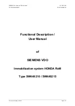
700 Series 2-Wire Wiring Diagram
NOTE:
Alarm contacts shown
in non-alarm mode.
Fire Alarm
Initiating Circuit
Compatible Listed
Control Unit
Screw terminal
enlargement detail
Continuity
Switch
Base 701U
for Head Model 711U
Base 702U or 702E
for all Head Models
Base 702RU, 702RE, 702U, or
702E; for Heads Model 731U
First Detector
Last Detector
Remote Test
Switch, N.O.
Remote LED
Blinks every 9 seconds during normal condition
Blinks once every second during trouble condition
Latches on in alarm
No indication during loss of power
Normally Open
Common
Normally Closed
End-of-Line
Device
1
3
2
6
4
5
1
3
2
6
4
5
+
–
NOTE: Alarm contacts shown
in non-alarm mode.
700 Series 4-Wire Wiring Diagram 741UT Head
Figure 1. Wiring diagrams
Remote LED
Blinks every 9 seconds during normal condition
Blinks once every second during trouble condition
Latches on in alarm
No indication during loss of power
First Detector
Last Detector
Continuity
Switch
Screw terminal
enlargement detail
End-of-Line
Device
Base 702U or 702E
(Relay in Head)
Base 702U or 702E
(Relay in Head)
Power Supervision
Unit (204-12/24V)
Red
Black
Brown
Brown
DC
Power
Circuit
Fire
Alarm
Initiating
Circuit
Installation
Placement and Spacing
Use the following location guidelines to optimize performance and reduce
the chance of false alarms:
• Locate ceiling-mounted smoke detectors in the center of a room or
hallway at least 4 inches (10cm) from any walls or partitions.
•
Locate wall-mounted smoke detectors so the top of the unit is 4 to 12
inches (10 to 30cm) below the ceiling. See Figure 1.
•
Locate in a suitable environment as follows:
- Temperature between 32°F (0°C) and 100°F (38°C)
- Humidity between 0 and 95% non-condensing
•
Locate away from air conditioners, heating registers, and any other
ventilation source that may interfere with smoke entering the unit.
•
Mount units on a firm permanent surface.
•
When more than one detector is required, spacing of 30 feet (9.1m)
may be used as a guide on smooth ceilings. Other spacing may be used
depending on ceiling height, high air movement, and other conditions
or response requirements.
•
Locate away from kitchens, wood stoves, garages, furnaces, and
bathrooms.
firealarmresources.com