background image

ITA 

 ENG 

 FRA 

 ESP 

 DEU 

 POR 

6-1624050 rev.12   14/11/2012                                                                                                                       Pag 1 di 9 
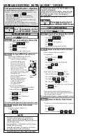


PRAKT/GAR.AS Catena 


L’automazione per portoni sezionali e basculanti 


Istruzioni di installazione e uso 


Questo manuale è stato redatto dal costruttore ed è parte integrante del prodotto. 
In queste pagine sono contenute tutte le informazioni necessarie per: 

• 

Un metodo di installazione che permetta di lavorare in sicurezza. 

• 

La corretta installazione dell’automazione. 

• 

La conoscenza della parte meccanica dell’ automazione. 

• 

Il corretto uso in condizioni di sicurezza. 

• 

La corretta manutenzione. 

Al fine di evitare movimentazioni errate con il rischio di incidenti, è necessario leggere attentamente 
questo manuale, seguendo passo dopo passo le informazioni fornite.  

Summary of Contents for PRAKT/GAR.AS 120

Page 1: ...pagine sono contenute tutte le informazioni necessarie per Un metodo di installazione che permetta di lavorare in sicurezza La corretta installazione dell automazione La conoscenza della parte meccani...

Page 2: ...odo stabile e duraturo e che l installazione non modifichi caratteristiche importanti dell ambiente circostante Le caratteristiche tecniche sono elencate nella tabella 1 e devono essere rispettate in...

Page 3: ...RVIZIO RESIDENZIALE 5 cicli h o 300s continui PRAKT GAR AS 60 4500 mm 8 Kg PRAKT GAR AS 120 ATTENZIONE Ogni intervento o messa in funzione iniziale deve essere eseguita esclusivamente da personale qua...

Page 4: ...ella DIRITTA in dotazione con l archet to Unire le varie parti della guida utilizzando le apposite aste fornite parti A e B Inserire inoltre i 4 blocchetti in plastica C D con il bullone rivolto verso...

Page 5: ...ungere durante il movimento e il bordo della guida ci sia una distanza pa ri ad almeno 2 cm punti 1 e 2 della figura 17 figura 18 L angolo a della figura 18 non pu essere inferiore ai 30 altrimenti no...

Page 6: ...il dado forniti figura 21 figura 21 Modificare le staffe di fissaggio fornite in modo da installare la guida a li vello La massima distanza ottenibile tra il soffitto e la guida con le staffe fornite...

Page 7: ...ar passare il cordino d acciaio dalla parte del capo senza fermo attra figura 26 figura 27 Inserire il cavetto nella guaina figura 27 e farlo scorrere attraverso di es sa completamente E consigliato i...

Page 8: ...itrave punto b ci devono essere 4 cm figura 31 figura 31 Fissare la squadretta A dell archetto adattatore sul bordo superiore del portone Il centro della squadretta deve corrispondere con il centro de...

Page 9: ...truttore declina ogni responsabilit in caso di inosservanza delle presenti avvertenze 4 2 Manutenzione automazione Si consiglia di far verificare periodicamente ad un tecnico specializzato l automazio...

Page 10: ......

Page 11: ...of the product In these pages are contained all the information necessary for A method of installation which allows to work in safety The correct installation of the automation The knowledge of the me...

Page 12: ...hat the automation can be fixed in a solid and lasting way and that the installation does not modify the important characteristics of the surrounding environment The technical data are listed on the t...

Page 13: ...ION DEGREE IP 40 SERVICE RESIDENTIAL 5 cycles h PRAKT GAR AS 60 PRAKT GAR AS 120 4500mm 8Kg WARNING Each intervention or beginning put on starting must be executed exclusively by qualified personnel T...

Page 14: ...ff fig 7 mounted on the sliding block with the one STRAIGHT supplied with the arc Link the various parts of the guide by using the suitable pro vided steels parts A and B Moreover insert the 4 plastic...

Page 15: ...which the door can reach during the movement and the board of the guide there is a distance just like at almost 2 cm point 1 and 2 of the fig 17 figure 18 The angle a of the figure 18 can not be infer...

Page 16: ...e supplied bolt and screw fig 21 figure 21 Modify the supplied fixing clamps in a way to install the drive to the level The maximum distance gettable between the ceiling and the drive with the supplie...

Page 17: ...of steel pass from the part of the head without stop through the eye present on the unblocking lever fig 26 figure 26 figure 27 Insert the wire inside the sheath fig 27 and make it slide through her c...

Page 18: ...lamp on the architrave point b they must be 4 cm fig 31 figure 31 Fix the bracket A of the adaptor bow on the superior board of the door The centre of the bracket must correspond with the centre of th...

Page 19: ...eclines all responsibilities in case of inobservance of these cautions 4 2 Maintenance of the automation It is advisable to make periodically check the automation by specialized technical personnel To...

Page 20: ......

Page 21: ...suivantes Vous trouverez toutes les informations n cessaires pour Une m thode d installation qui Vous permettra de travailler en toute s curit La correcte installation de l automation La connaissance...

Page 22: ...itat environnant Les caract ristiques techniques sont report es dans le tableau 1 et doivent toujours tre respect es Pour le programme d entretien suivre exclusivement le chapitre entretien pr sent da...

Page 23: ...N IP 40 SERVICE RESIDENCIEL 5 cycle h ou 300s continus PRAKT GAR AS 60 4500 mm 8 Kg PRAKT GAR AS 120 ATTENTION Chaque intervention et la mise en marche initial doit tre effectu e par un personnel qual...

Page 24: ...atin avec la tige droite fournie avec l arc Unir le pi ce du rail en utilisant les tiges fournies c t s A et B Ins rer en outre les 4 blochets en plastique C D avec les boulons tourn s vers l ext rieu...

Page 25: ...ndre pendant son mouvement et le bord du rail il y ai une distance d au moins 2 cm points 1 et 2 de la figure 17 figura 18 L angle a de la figure 18 ne doit pas tre inf rieur 30 sinon la transmission...

Page 26: ...ournis figure 21 figure 21 Modifier les tiges de fixation fournies de mani re installer le rail ni veau La distance maximum que l on puisse obtenir entre le toit et le rail est de 45cm Pour obtenir un...

Page 27: ...vers le trou pr sent sur le levier de d blocage figure 26 figure 26 figure 27 Ins rer le c ble dans la gaine figure 27 et faite le glisser compl tement travers celle ci Il est conseill de graisser le...

Page 28: ...ir une distance de 4 cm figure 31 figure 31 Fixer l querre A de l arc adaptateur sur le bord sup rieur du portail Le centre de l querre doit correspondre avec le centre du rail Fixer le point B du bra...

Page 29: ...ilit dans le cas ou ces avertissements ne viennent pas respect s 4 2 Entretien de l automation On conseille de faire v rifier p riodiquement l automation un technicien sp cialis Pour assurer un foncti...

Page 30: ......

Page 31: ...tas p ginas contienen todas las informaci nes necesarias por Un metodo de instalaci n que permita de trabajar en seguridad La correcta instalaci n de la automaci n El conocimiento de la parte mecanica...

Page 32: ...nera estable y duradera y que la instalaci n no modifique caracterist cas importantes del ambiente circunstante Las caracter sticas tecnicas son elencadas en la tabla 1 y deben ser respectadas en cual...

Page 33: ...IO RESIDENCIAL 5 ciclos h o 300s continuos PRAKT GRA AS 60 PRAKT GRA AS 120 4500 mm 8 Kg ATENCI N Cada intervenci n o puesta en funcionamiento inicial debe ser ejecutada exclusivamente por personal ca...

Page 34: ...aci n con el arco Juntar las varias partes de la gu a utilizando los v stagos apropiados en dotaci n partes A y B Insertar adem s los 4 bloques en plastico C D con el perno dirigido hacia el externo H...

Page 35: ...ta en apertura y tambien en cerrada la estafa de conexi n entre la puerta y el carro de enganche no interfiera con las partes en movimento La distancia entre el borde m s bajo de la gu a y el borde su...

Page 36: ...nillo y la tuerca en dotaci n figura 21 figura 21 Modificar las estafas de fisaje en dotaci n en manera tal que la gu a sea instalada a nivel La m xima distancia alcanzable entre el techo y la gu a co...

Page 37: ...ero de la parte del cabo sin par a tra vez de la argilla presente sobre la palanca de desbloqueo figura 26 figura 26 figura 27 Insertar el cable en en la vaina figura 27 y hacerlo correr a travez de e...

Page 38: ...maestra punto b hay qye haber 4 cm figura 31 figura 31 Fijar la escuadra A del arco adaptator sobre el borde superi r de la puerta El centro de la escuadrs debe corresponder con el centro de la gu a...

Page 39: ...lidad en caso de inobservancia de las presentes advertencias 4 2 Manutenci n de la automaci n Se aconseja de hacer verificar periodicamente a un tecnico especializado la automaci n Para asegurar un fu...

Page 40: ......

Page 41: ...lle notwendigen Daten f r Eine Installationsmethode die ein sicheres Arbeiten erm glicht Die korrekte Installation der Anlage Das Kennen lernen des mechanischen Teils und der Elektronik der Automation...

Page 42: ...rt worden ist Die technischen Eigenschaften k nnen der Tabelle 1 entnommen werden und m ssen in jedem Fall beachtet werden F r eine Programmierung der Instandhaltung halten Sie sich ausschliesslich an...

Page 43: ...m Beleuchtung 24V MAX 20W Schutzgrad IP 40 Benutzung Privatbereich 5 Zyklen St Oder 300 sek PRAKT GAR AS 60 Kette PRAKT GAR AS 120 Kette 4500mm 8Kg ACHTUNG Jegliches Eingreifen oder Installierung muss...

Page 44: ...wechselt werden Abb 7a Beide Laufschinen mit den Verbindungselementen zu sammenmontieren Siehe A und B Montieren Sie ausser dem die Plastikbl cke C D mit dem Schraubenkopf nach innen Schiben Sie das g...

Page 45: ...Abb 15 und 16 Bitte sehen Sie einen Mindestab stand von 3 mm zwischen der Schiene und der Decke vor Abb 10 Abb 11 Abb 12 Abb 13 Abb 14 berpr fen Sie jetzt die richtige Spannung der Kette indem Sie au...

Page 46: ...chen einen maximalen Abstand von 45cm zwischen der Laufschiene und der Decke Der berfl ssige Teil soll weggeschnitten werden Abb 22 Abb 18 Der Winkel a der Abbildung 18 darf nicht weniger als 30 sein...

Page 47: ...er Pa ckung bei F hren Sie den Seilzug durch das Loch am Entriegelungshebel Abb 26 ein Abb 26 Abb 27 Schieben Sie den Seilzug in die T lle Abb 27 Wir empfehlen den Seil zug ein wenig zu schmieren um d...

Page 48: ...te 4 cm sein siehe Abb 31 Abb 31 Befestigen Sie den Winkel A des Adaptors an die Oberkante des Ga ragentores Der Winkel muss genau in der Mitte sitzen Den Punkt B des Adaptors am Tor befestigen Kontro...

Page 49: ...ion periodisch vom Fachmann pr fen zu lassen Insbesondere auf folgendes achten Kontrollieren Sie regelm ssig die korrekte Balancierung des Tores Zu diesem Zweck bet tigen Sie die Notentriegelung ffnen...

Page 50: ......

Reviews: