background image

E

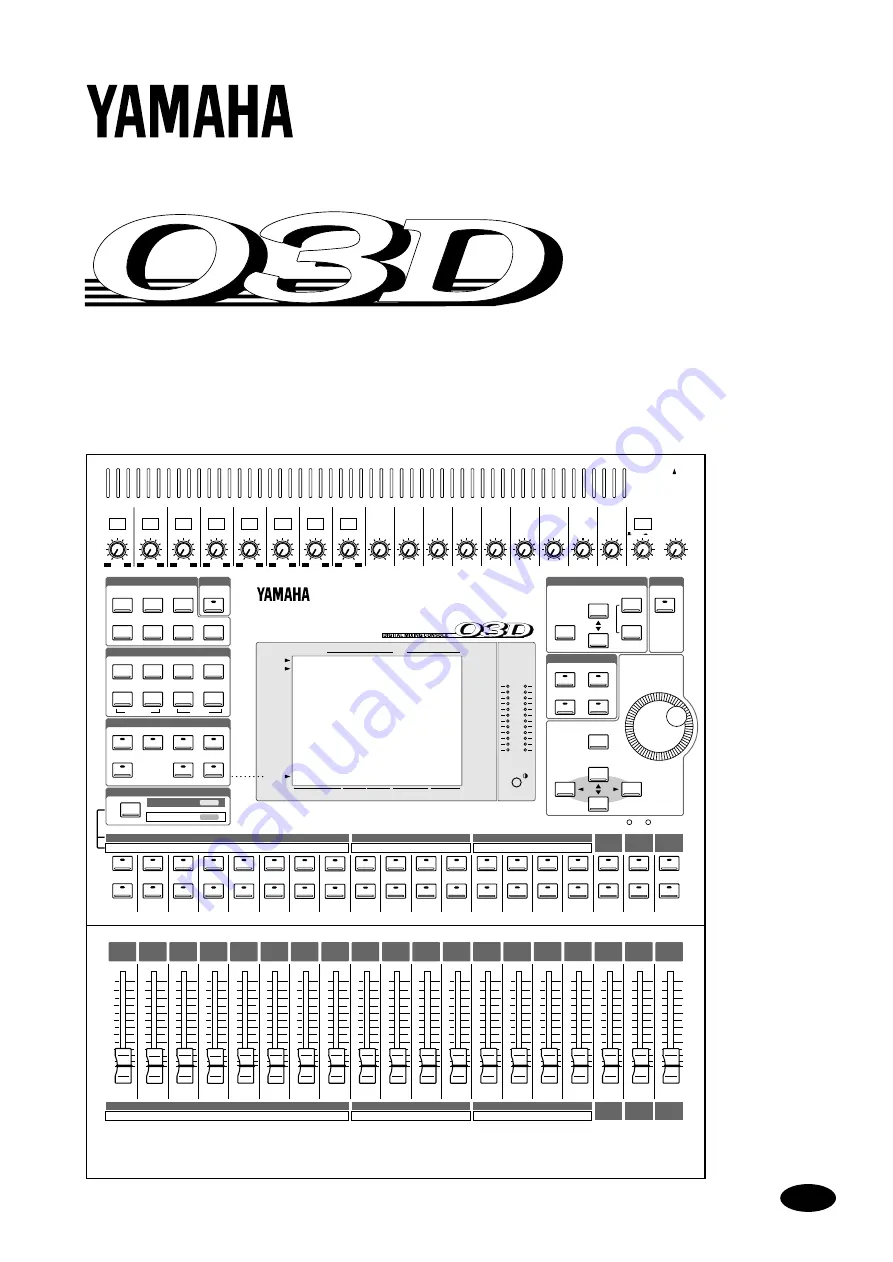
DIGITAL MIXING CONSOLE

Owner’s Manual

PHONES

PHONES

+10

–34

–60

–16

26dB

1

+10

–34

–60

–16

26dB

2

+10

–34

–60

–16

26dB

3

+10

–34

–60

–16

26dB

4

+10

–34

–60

–16

26dB

5

+10

–34

–60

–16

26dB

6

+10

–34

–60

–16

26dB

7

+10

–34

–60

–16

26dB

8

+10

–20

+10

9

GAIN

+10

–20

+10

10

GAIN

+10

–20

+10

11

GAIN

+10

–20

+10

12

GAIN

+10

–20

+10

13

GAIN

+10

–20

+10

14

GAIN

+10

–20

+10

15

GAIN

+10

–20

+10

16

GAIN

+10

–20

+10

ST IN

GAIN

GAIN

GAIN

GAIN

GAIN

GAIN

GAIN

GAIN

GAIN

10

0

SOLO/     2TR IN

MONITOR

OUT

LEVEL

10

0

LEVEL

SCENE MEMORY

SETUP

CHANNEL CONTROL

FADER MODE

MIXING LAYER

1–16

17–24/MASTER

USER DEFINE

SOLO

RECALL

ENTER

L STEREO R

USER DEFINE

EFFECT RTN

ST IN

13–16

9–12

FADER 1–8

SCENE MEMORY

FUNCTION

SEL CH

FADER

STATUS

SCENE

MEMORY

MIDI

REMOTE

UTILITY

AUTOMIX

VIEW

HIGH

HI-MID

LO-MID

EQ LOW

AUX 1

FADER

EFFECT 1

EFFECT 2

AUX 2

AUX 3

AUX 4

EQ LIBRARY

SOLO SETUP

GROUP/PAIR

DYNAMICS

DELAY/Ø

PAN/ROUTING

MIDI

DIO

PARAMETER

CURSOR

STORE

UNDO/

REDO

CLIP

–3

–6

–9

–12

–15

–18

–24

–30

–36

–42

–48

SEL

ON

SEL

ON

SEL

ON

SEL

ON

SEL

ON

SEL

ON

SEL

ON

SEL

SEL

ON

ON

SEL

ON

SEL

ON

SEL

ON

SEL

ON

SEL

ON

SEL

ON

SEL

ON

SEL

ON

SEL

ON

SEL

ON

1

2

3

4

5

6

7

8

9

10

11

12

13

14

15

16

ST IN

EFFECT

RETURN

ST OUT

17

18

19

20

21

22

23

24

AUX1

AUX2

AUX3

AUX4

BUS1

BUS2

BUS3

BUS4

1

2

3

4

5

6

7

8

9

10

11

12

13

14

15

16

ST IN

EFFECT

RETURN

ST OUT

17

18

19

20

21

22

23

24

AUX1

AUX2

AUX3

AUX4

BUS1

BUS2

BUS3

BUS4

6

0

5

10

20

40
60

00

6

0

5

10

20

40
60

00

6

0

5

10

20

40
60

00

6

0

5

10

20

40
60

00

6

0

5

10

20

40
60

00

6

0

5

10

20

40
60

00

6

0

5

10

20

40
60

00

6

0

5

10

20

40
60

00

6

0

5

10

20

40
60

00

6

0

5

10

20

40
60

00

6

0

5

10

20

40
60

00

6

0

5

10

20

40
60

00

6

0

5

10

20

40
60

00

6

0

5

10

20

40
60

00

6

0

5

10

20

40
60

00

6

0

5

10

20

40
60

00

6

0

5

10

20

40
60

00

6

0

5

10

20

40
60

00

6

0

5

10

20

40
60

00

SOLO

1

2

PAD

EQ FLAT

METER

1

2

3

4

Summary of Contents for 03D

Page 1: ... AUX 4 EQ LIBRARY SOLOSETUP GROUP PAIR DYNAMICS DELAY Ø PAN ROUTING MIDI DIO PARAMETER CURSOR STORE UNDO REDO CLIP 3 6 9 12 15 18 24 30 36 42 48 SEL ON SEL ON SEL ON SEL ON SEL ON SEL ON SEL ON SEL SEL ON ON SEL ON SEL ON SEL ON SEL ON SEL ON SEL ON SEL ON SEL ON SEL ON SEL ON 1 2 3 4 5 6 7 8 9 10 11 12 13 14 15 16 ST IN EFFECT RETURN ST OUT 17 18 19 20 21 22 23 24 AUX1 AUX2 AUX3 AUX4 BUS1 BUS2 BU...

Page 2: ...isesti asennettu Vaihda paristo ainoastaan laitevalmistajan suosittelemaan tyyppiin Hävitä käytetty paristo valmistajan ohjeiden mukaisesti FCC INFORMATION U S A 1 IMPORTANT NOTICE DO NOT MODIFY THIS UNIT This product when installed as indicated in the instructions contained in this manual meets FCC requirements Modifications not expressly approved by Yamaha may void your authority granted by the ...

Page 3: ...ide the 03D are a fire and electrical shock hazard Do not block the 03D ventilation holes The 03D has ventilation holes at the top and rear to prevent the internal temperature from rising Blocked ventilation holes are a fire hazard Do not try to modify the 03D This could be a fire and electrical shock hazard The 03D operating temperature is between 5 C and 35 C 41 F and 95 F Cautions Turn off all ...

Page 4: ...o Logic are trademarks of Dolby Laboratories Licensing Corpora tion Copyright 1992 Dolby Laboratories Inc All rights reserved Fostex and RD 8 are trademarks of Fostex Corporation Macintosh is a registered trademark of Apple Computer Inc Pro Tools is a registered trademark of Digidesign or Avid Technology Inc Tascam Digital Interface is a trademark and Tascam and TEAC are registered trade marks of ...

Page 5: ...R Button 29 Mouse 30 Mixing Layer 31 Title Edit Dialog Box 33 4 Input Channels 35 Input Channel Overview 36 Phantom Power input channels 1 8 37 Pad input channels 1 8 37 Gain 37 Metering 37 Insert input channels 1 2 37 Attenuator 38 Phase 39 Channel Delay 40 Applying EQ to the Input Channels EQ 42 Dynamics Processor 42 Muting Input Channels ON OFF 42 Setting Input Channel Levels 42 Pan Balance Rou...

Page 6: ...k Input 77 Solo Block Diagram 78 Metering 79 Monitor Block Diagram 82 8 Stereo Output 83 About the Stereo Output 84 Analog Stereo Outputs 84 DIGITAL STEREO OUT 84 Stereo Output the YGDAI Interface 84 Rec Out the Stereo Output 84 Solo the Stereo Output 84 Monitoring the Stereo Output 84 Metering the Stereo Output 84 Routing Signals to the Stereo Output 84 Setting the Stereo Output Level 85 Muting t...

Page 7: ...9 Applying EQ to Bus Outs 99 Bus Out Dynamics Processors 99 Bus Out Delay 100 Routing Bus Signals to the Stereo Bus 101 Bus Out Stereo Pairs 101 Bus Out Block Diagram 102 11 Channel Library View 103 Channel Library 104 Storing Channel Programs 105 Recalling Channel Programs 106 Editing Channel Program Titles 107 Channel View 108 12 Groups Pairs 111 Fader Groups 112 Mute Groups 113 Stereo Pairs 114...

Page 8: ... Mix Scene Recalls 169 Write Protecting Scene Memories 170 Editing Scene Memory Titles 171 Sorting Scene Memories 172 Setting a Fade Time 173 Recalling Scene Data Safely 174 16 Automix 175 About Automix 176 Creating a New Automix 180 Enabling Automix 180 Setting the Time Base 181 Setting an Automix Offset 182 Safe Channels 183 Selecting Parameters for Recording 184 Recording an Automix 185 Playing...

Page 9: ...HOST Data Receive Indicators 233 MIDI HOST Setup 233 MIDI Setup 235 MIDI Monitor 238 Program Change Assign 239 Control Change Assign 240 System Exclusive Parameter Control 241 Bulk Dump 242 MIDI Remote 243 Troubleshooting 251 Appendix A General 253 03D Level Diagram 253 Display Messages 254 Security Cover 256 Rack mounting Kit 256 03D VEK Video Edit Suite Software 256 Appendix B Specifications 257...

Page 10: ...03D Owner s Manual Appendix C MIDI 267 Scene Memory to Program Change Table 267 Parameter to Control Change Table 268 MIDI Data Format 271 Appendix D Resources 279 Books 279 Yamaha Web Site 279 Glossary 281 Index 285 ...

Page 11: ...Welcome to the 03D 1 03D Owner s Manual Welcome to the 03D 1 In this chapter Welcome to 03D 2 About this Owner s Manual 2 03D Installation 2 03D Features 3 Key Feature Discussion 4 ...

Page 12: ...elated jargon is provided on page 281 Each chapter in this manual discusses a single area of the 03D For example Input Channels explains all about input channels while Scene Memories explains all about scene memories The contents of most chapters are obvious from the chapter title Rather than repeat some explanations several times items that are common to many channels such as EQ and the dynamics ...

Page 13: ...mprehensive monitoring Four fader groups for multiple channel control Four mute groups for multiple channel muting Stereo pair operation for input channels aux sends and bus outs Four band parametric EQ on virtually every input and output 160 bands of EQ Powerful EQ library with 40 preset programs and 40 user programs Four aux sends with analog outputs Two onboard effects processors with 64 preset...

Page 14: ...l realm audio mixing consists of adding and multiplying binary numbers that represent audio signals The DSP Digital Signal Processor chips used for these calculations never get their sums wrong So once past the initial A D conversion audio signals are immune from signal degradation With the 03D noise distortion and crosstalk are virtually eliminated You ll hear a new clarity in your mixes Once in ...

Page 15: ...hannels configured as a stereo pair move simultaneously See Stereo Pairs on page 114 for more information The ST OUT and ST IN faders always control the stereo output and stereo input chan nel levels respectively The EFFECT RETURN fader controls the return levels of the two onboard effects processors The operation of faders 1 to 16 however depends on the selected mixing layer When the mixing layer...

Page 16: ... or DA38 and AES EBU andYamaha Y2 format equipment SeeYGDAI Cards on page 223 for more information In addition AES EBU and Coaxial digital stereo inputs and outputs allow direct con nection to digital recorders and other digital devices Digital stereo signals can be routed to the Stereo bus for cascade operation or to the stereo input channel for mixing and processing See Digital Stereo In on page...

Page 17: ...der moves can be edited on the fly or off line using the Trim function The Undo function can be used to revert to the previous automix after making changes that you do not want to keep MIDI In addition to standard MIDI connectors the 03D features a TO HOST connector This allows the 03D to be connected directly to a personal computer without a MIDI inter face By connecting other MIDI gear to the 03...

Page 18: ...8 Chapter 1 Welcome to the 03D 03D Owner s Manual ...

Page 19: ...Touring the 03D 9 03D Owner s Manual Touring the 03D 2 In this chapter Top Panel 10 Rear Panel 16 Block Diagram 21 ...

Page 20: ... MID EQ LOW AUX 1 FADER EFFECT 1 EFFECT 2 AUX 2 AUX 3 AUX 4 EQ LIBRARY SOLOSETUP GROUP PAIR DYNAMICS DELAY Ø PAN ROUTING MIDI DIO PARAMETER CURSOR STORE UNDO REDO CLIP 3 6 9 12 15 18 24 30 36 42 48 SEL ON SEL ON SEL ON SEL ON SEL ON SEL ON SEL ON SEL SEL ON ON SEL ON SEL ON SEL ON SEL ON SEL ON SEL ON SEL ON SEL ON SEL ON SEL ON 1 2 3 4 5 6 7 8 9 10 11 12 13 14 15 16 ST IN EFFECT RETURN ST OUT 17 ...

Page 21: ...e level of the signals appearing at the MONITOR OUT connectors The signal source is set using the adjacent MONITOR OUT switch E PHONES LEVEL control This control is used to adjust the phones level The signal source is set using the MON ITOR OUT switch PHONES PHONES 10 34 60 16 26dB 1 10 34 60 16 26dB 2 10 34 60 16 26dB 3 10 34 60 16 26dB 4 10 34 60 16 26dB 5 10 34 60 16 26dB 6 10 34 60 16 26dB 7 1...

Page 22: ...o that the display is clear and easy to read from your viewing position You may need to readjust it when viewing the display from a different height or angle Setup The Setup function buttons are used to access the following setup and configuration pages The name of the selected function is shown on the display Button Pages SCENE MEMORY Scene Mem Fade Time RCL Safe Sort UTILITY Oscillator Prefer Us...

Page 23: ...163 for more information Button Pages DELAY CH Delay Dly 1 16 Dly 17 24 Output Dly Phase DYNAMICS Dyn Edit Library PAN ROUTING Pan 1 16 Pan 17 24 Surround Bus to ST when a surround pan mode is selected the Bus to ST page is replaced by the Surr 1 16 and Surr 17 24 pages VIEW CH View Library EQ LOW LO MID HI MID HIGH EQ EQ LOW LO MID EQ Library Button Fader Mode Pages AUX 1 CH AUX 1 send AUX 1 Pre ...

Page 24: ...75 for more information User Define The USER DEFINE buttons are user programmable buttons that can be configured to send specific MIDI or MMC MIDI Machine Control commands when pressed They can also be used to recall frequently used mix scenes or effects programs adjust mix set tings of the selected channel or control the Automix function These buttons are con figured on the User Def page See User...

Page 25: ...Mixing Layer See ON Buttons on page 31 for more information When the SOLO function is on ON buttons work as solo buttons not mute buttons D Faders The faders are used to adjust input channel and output channel levels The 03D features 60 mm motorized faders The function of each fader depends on the selected fader mode and Mixing Layer See Faders on page 32 for more information The selected fader mo...

Page 26: ...ring is supplied to the XLR connector The phone jack has prior ity over the XLR type connector so when a phone plug is inserted the XLR type con nector is disconnected The phone jack inputs can also be used with unbalanced phone plugs With their high sensitivity and 26 dB PAD switches these inputs can handle a wide range of signals from condenser microphones to hot line levels 3 1 2 1 2 3 ST OUT R...

Page 27: ...el signals G MONITOR OUT These are balanced 1 4 inch phone jacks with a 4 dB nominal output level Either balancedorunbalancedphoneplugscanbe connected They output the monitor sig nals and should be connected to the inputs on a monitor amplifier The monitor signal source is determined by the MONITOR OUT SOLO 2TR IN switch The output level is set using the MONITOR LEVEL con trol H BUS OUTs These are...

Page 28: ...elect the signal source ST OUT or BUS 1 and BUS 2 They can be connected to a cassette DAT or other recorder K ST OUT These are balanced XLR 3 32 type connectors with a 4 dB nominal output level They are wired pin 1 ground pin 2 hot and pin 3 cold They output the main ste reo mix If you need to connect the balanced ST OUT to an unbalanced phone jack input use a cable with the following wiring schem...

Page 29: ...o be used with various wordclock wiring schemes See Wordclock Setup on page 216 E DIGITAL STEREO OUT These two connectors are digital stereo outputs They output the same digital audio sig nal but in different formats The XLR 3 32 type connector outputs AES EBU format digital audio 24 bit while the COAXIAL connector outputs Consumer format digital audio 20 bit F DIGITAL STEREO IN These two connecto...

Page 30: ...tandard MIDI IN OUT and THRU connections They are used to connect the 03D to other MIDI equipment for control and synchronization I YGDAI slot An optional YGDAI card can be installed here providing access to the 03D s eight dig ital inputs and outputs See YGDAI Cards on page 223 ...

Page 31: ...amics 4Band PEQ 4Band PEQ 4Band PEQ DELAY DA Dynamics 4Band PEQ Meter DA PAN DA Meter DELAY Dynamics from EFF2 from EFF1 EFF 1 2 INTERNAL EFFECT 1 INTERNAL EFFECT 2 Meter Dynamics 4Band PEQ 4Band PEQ Dynamics Meter PAN PAN INDIVIDUAL GANG INVERTED GANG PAN Meter De Emphasis DELAY EFFECT DELAY EFFECT Meter Dynamics 4Band PEQ 4Band PEQ Dynamics HA AD DC CUT GAIN HA AD DC CUT AUX 1 2 3 4 BUS 1 2 3 4 ...

Page 32: ...22 Chapter 2 Touring the 03D 03D Owner s Manual ...

Page 33: ...23 03D Owner s Manual Getting Around the User Interface 3 In this chapter About the User Interface 24 Display 24 Display Elements 28 Cursor Buttons 29 PARAMETER Wheel 29 ENTER Button 29 Mouse 30 Mixing Layer 31 Title Edit Dialog Box 33 ...

Page 34: ...rameter values numerically faders and rotary controls are represented graphically so you can actually see pan and fader positions The display also shows EQ curves and provides signal level meters The following illustration highlights the different areas of the display These areas are explained below Scene memory This area of the display shows the selected scene memory number and title whether or n...

Page 35: ...is set to 17 24 MASTER the following channels are metered Menu button The Menu button is used in conjunction with a mouse to access the Menu Function See Function Menu on page 30 for more information Page area This area of the display is where the various setup configuration and mixing function pages appear As well as showing parameter values numerically faders and rotary controls are represented ...

Page 36: ...hows the selected fader mode and Mixing Layer The top row indicates which channel the fader is controlling e g channel 1 and the bottom row indicates which signal of that channel the fader is controlling e g AUX 1 SEND The following two tables show what is displayed for the various fader modes and Mixing Layer settings Mixing Layer 1 16 Selected page FADER METER EFFECT RTN ST IN 13 16 9 12 FADER 1...

Page 37: ... IN 13 16 9 12 FADER 1 8 FADER METER EFFECT RTN ST IN 13 16 9 12 FADER 1 8 AUX 1 EFFECT RTN ST IN 13 16 9 12 FADER 1 8 AUX 2 EFFECT RTN ST IN 13 16 9 12 FADER 1 8 AUX 3 EFFECT RTN ST IN 13 16 9 12 FADER 1 8 AUX 4 EFFECT RTN ST IN 13 16 9 12 FADER 1 8 EFFECT 1 EFFECT RTN ST IN 13 16 9 12 FADER 1 8 EFFECT 2 EFFECT RTN ST IN 13 16 9 12 FADER 1 8 ...

Page 38: ...o adjust the value To adjust a rotary control using a mouse position the mouse cursor over the control press and hold the left mouse button and then drag the mouse Parameters with a wide range such as effects delay times can be adjusted much quicker by holding down the right mouse button and dragging Rotary con trols can also be adjusted in single step increments by clicking once with a mouse Clic...

Page 39: ... to see which parameter or option is currently selected Holding down a cursor button moves the cursor continuously in the respective direction PARAMETER Wheel The PARAMETER wheel is used to adjust parameter values scroll through scene memory and library programs and posi tion the cursor when titling scene memories effects programs and so on Its detented action gives it a positive feel allowing qui...

Page 40: ...es canbeadjustedmuchquickerbyholdingdownthe right mouse button and dragging In this case the left mouse button works like a fine adjust control while the right mouse button works as a coarse adjust control Parameters can also be adjusted in single step increments by clicking once with the mouse Clicking with the left mouse button decreases a value clicking with the right button increases it Displa...

Page 41: ... SOLO function is on input channels 1 to 24 the stereo input channel and effects returns channel s ON buttons work as solo buttons not mute buttons ON button operation is different in MIDI Remote mode See MIDI Remote on page 243 for more information 1 During automix recording the EFFECT RETURN SEL button is used to turn effect edit ing on and off In this case the EFFECT 1 and EFFECT 2 buttons shou...

Page 42: ...UX 2 send EFF RTN 1 2 AUX 2 send Aux 3 CH 1 8 AUX 3 send CH 9 12 AUX 3 send CH 13 16 AUX 3 send ST IN AUX 3 send EFF RTN 1 2 AUX 3 send Aux 4 CH 1 8 AUX 4 send CH 9 12 AUX 4 send CH 13 16 AUX 4 send ST IN AUX 4 send EFF RTN 1 2 AUX 4 send Effect 1 CH 1 8 Eff 1 send CH 9 12 Eff 1 send CH 13 16 Eff 1 send ST IN Eff 1 send EFF RTN 1 fader Effect 2 CH 1 8 Eff 2 send CH 9 12 Eff 2 send CH 13 16 Eff 2 s...

Page 43: ...r a character use the cursor buttons to select a character and then press the ENTER button If you are using a mouse simply click a char acter To access the lowercase characters and various symbols select the SHIFT LOCK switch and press the ENTER button Press SHIFT LOCK again to access the uppercase characters and numbers Use the INS switch to insert a space at the cursor position and move sub sequ...

Page 44: ...34 Chapter 3 Getting Around the User Interface 03D Owner s Manual ...

Page 45: ...els EQ 42 Dynamics Processor 42 Muting Input Channels ON OFF 42 Setting Input Channel Levels 42 Pan Balance Routing 42 Direct Outputs 43 Aux Sends 43 Monitoring Input Channels 43 Input Channel Stereo Pairs 43 Input Channels Block Diagram 44 This chapter covers input channels 1 to 24 and the stereo input ST IN Unless other wise stated explanations refer to all of these inputs The sections of this c...

Page 46: ...xcept they do not have inserts XLR inputs or phantom powering Input Channels 17 to 24 Input channels 17 to 24 are identical to input channels 9 to 16 except they do not have analog input connectors a pad switch gain control or direct out These input channels are accessed through the digital inputs of the YGDAI slot See YGDAI Cards on page 223 for more information Stereo Input Channel ST IN Apart f...

Page 47: ... s set too low the signal to noise performance will suffer If it s set too high unpleasant signal clipping and distortion may occur The GAIN controls on input channels 1 to 8 are designed for use with microphone signals and have an input sensitivity of 16 dB to 60 dB Used in conjunction with the 26 dB PAD switches however these chan nels can also be used with line level signals and hot microphone ...

Page 48: ...r the ATT control press and hold the left mouse button and then drag the mouse The Attenuation function can be used to compensate for level increases caused by EQ boosting or dynamics processing Instead of using a GAIN control to reduce a boosted signal it s better to use the Attenuation function Although levels can be reduced using the GAIN controls this also reduces the level of the signal being...

Page 49: ...hone can be phase reversed 1 Use the DELAY button to locate the Phase page shown below 2 Use the SEL and MIXING LAYER buttons to select a channel See Mix ing Layer on page 31 for more information 3 Use the ENTER button to set the phase of the selected channel You can also use the cursor button to select the phase switches If you are using a mouse simply click the phase switches Phase switches can ...

Page 50: ...y without having to select the ON OFF switch TYPE These switches are used to select the type of delay DELAY SLAP or ECHO The echo parameters are reset when the type of delay is changed PARAMETER The controls in this window are delay parameter controls The num ber of controls available depends on type of delay selected When the type of delay is changed from Delay to either Slap or Echo the paramete...

Page 51: ...he DELAY button to locate these pages The following page shows the delay settings for input channels 1 to 16 The following page shows the delay settings for input channels 17 to 24 and the stereo input channel These pages show the type of delay and delay time set for each channel These settings cannot be changed on these pages The delays can however be turned on and off 2 Use the SEL buttons to se...

Page 52: ... stereo input channel levels are controlled using the faders The function of each fader depends on the selected fader mode and Mixing Layer See Faders on page 32 for more information The selected fader mode is shown on the display See Display on page 24 for more information The stereo input channel fader is affected by the fader modes but not the Mixing Layer 1 Press the FADER button The Meter pag...

Page 53: ...ux sends are configured as a stereo pair aux send pan controls are activated on the input channels stereo input channel and effects returns See Aux Send Stereo Pairs on page 94 for more information Monitoring Input Channels See Solo Monitors Meters on page 71 for more information Input Channel Stereo Pairs Odd and even input channels from 1 to 24 can be paired for stereo operation This makes it ea...

Page 54: ...ELAY EFFECT Meter Dynamics 4Band PEQ 4Band PEQ Dynamics HA AD DC CUT GAIN HA AD DC CUT AUX 1 2 3 4 BUS 1 2 3 4 DC CUT AD HA GAIN GAIN HA PHANTOM PAD 26dB AD DC CUT Meter CH Fader ST IN Fader Dynamics 4Band PEQ DELAY Meter ATT DC CUT AD IN INSERT 26dB PAD PHANTOM 1 2 PAN AUX EFF PRE POST AUX 1 AUX 2 AUX 3 AUX 4 EFF 1 EFF 2 AUX 1 AUX 2 AUX 3 AUX 4 EFF 1 EFF 2 HA GAIN Meter Meter ATT BALANCE Same as ...

Page 55: ...l EQ 5 In this chapter About 03D EQ 46 Adjusting the EQ 47 Bypassing the EQ 47 Resetting the EQ Gain Controls 47 EQ Library 48 Storing EQ Programs 49 Recalling EQ Programs 50 Editing EQ Program Titles 51 Preset EQ Programs 52 ...

Page 56: ...d can be configured for shelving peaking or LPF Low Pass Filter operation When channels are configured as a stereo pair using the Pair function Stereo Pairs on page 114 the EQ sections including attenuators of the two channels work together and parameter adjustments can be made with either channel selected You cannot set different parameters for the odd and even channels EQ settings can be stored ...

Page 57: ...sts the EQ specs Bypassing the EQ To bypass the EQ for the selected channel simply press the ENTER button Press again to turn the EQ back on On the EQ page the ENTER button can be used to bypass the EQ regardless of the cursor position If you are using a mouse simply click the EQ ON switch on the EQ page Resetting the EQ Gain Controls To reset the EQ gain controls for the selected channel press th...

Page 58: ...then recalled to an aux send EQ The unique collection of preset EQ programs are designed for specific appli cations and instruments and provide a good reference and starting point when making EQ adjustments See page 52 for a complete list of the preset EQ programs The EQ library is controlled from the Library page shown below Press the EQ LOW and LO MID buttons together to access the Library page ...

Page 59: ...ist of EQ programs If you are using a mouse position the mouse cursor over the parameter box press and hold the left mouse button and then drag the mouse As each program is selected its EQ curve appears in the EQ CURVE window EQ pro grams that do not contain data have the title No Data 4 Use the cursor button to select the STORE switch and then press the ENTER button If you are using a mouse simpl...

Page 60: ... EQ program 3 Use the PARAMETER wheel to scroll through the list of EQ programs If you are using a mouse position the mouse cursor over the parameter box press and hold the left mouse button and then drag the mouse As each program is selected its EQ curve appears in the EQ CURVE window EQ pro grams that do not contain data have the title No Data 4 Use the cursor button to select the RECALL switch ...

Page 61: ...s the EQ LOW and LO MID buttons together to access the Library page 2 Select the EQ program using the PARAMETER wheel or mouse 3 Use the cursor buttons to select the TITLE EDIT switch and then press the ENTER button If you are using a mouse simply click the TITLE EDIT switch The Title Edit dialog box appears 4 Edit the program title See Title Edit Dialog Box on page 33 for more information 5 When ...

Page 62: ... attack of tom toms and creates a long leathery decay G 2 0 dB 7 5 dB 2 0 dB 1 0 dB F 210 Hz 667 Hz 4 49 kHz 6 35 kHz Q 1 4 10 1 2 0 28 06 Cymbal L SHELF PEAKING PEAKING H SHELF Emphasizes the attack of crash cymbals extend ing the sparkling decay G 2 0 dB 0 0 dB 0 0 dB 3 0 dB F 105 Hz 420 Hz 1 05 kHz 13 4 kHz Q 8 0 9 07 High Hat L SHELF PEAKING PEAKING H SHELF Use on a tight high hat emphasizing ...

Page 63: ...ng an electric guitar or semi acoustic guitar to get a slightly hard sound G 2 0 dB 5 5 dB 0 5 dB 2 5 dB F 265 Hz 397 Hz 1 33 kHz 4 49 kHz Q 0 18 10 6 3 16 E G Crunch 1 PEAKING PEAKING PEAKING PEAKING Adjusts the tonal qual ity of a slightly distorted guitar sound G 4 5 dB 0 0 dB 4 0 dB 2 0 dB F 140 Hz 1 00 kHz 1 88 kHz 5 65 kHz Q 8 4 5 0 63 9 17 E G Crunch 2 PEAKING PEAKING PEAKING H SHELF A vari...

Page 64: ... to the voice quality G 0 5 dB 0 0 dB 2 0 dB 3 5 dB F 187 Hz 1 00 kHz 2 00 kHz 6 72 kHz Q 0 11 4 5 0 56 0 11 26 Male Vocal 2 PEAKING PEAKING PEAKING H SHELF A variation on program 25 G 2 0 dB 5 0 dB 2 5 dB 4 0 dB F 167 Hz 236 Hz 2 67 kHz 6 72 kHz Q 0 11 10 5 6 27 Female Vo 1 PEAKING PEAKING PEAKING PEAKING Use as a template for female vocal Adjust the HIGH or H MID setting according to the voice q...

Page 65: ...n program 5 Emphasizes the mid and high range G 9 0 dB 1 5 dB 2 0 dB 0 0 dB F 88 Hz 210 Hz 5 33 kHz 16 9 kHz Q 4 5 1 2 36 Piano 3 PEAKING PEAKING PEAKING H SHELF A variation on program 13 G 4 5 dB 13 0 dB 4 5 dB 2 5 dB F 99 Hz 472 Hz 2 37 kHz 10 0 kHz Q 8 10 9 37 Piano Low PEAKING PEAKING PEAKING H SHELF Use for the low range of a piano sound recorded in stereo G 5 5 dB 1 5 dB 6 0 dB 0 0 dB F 187 ...

Page 66: ...56 Chapter 5 EQ 03D Owner s Manual ...

Page 67: ...Routing Surround Pan 57 03D Owner s Manual Pan Routing Surround Pan 6 In this chapter Selecting a Pan Mode 58 Stereo Pan Balance Routing 59 Stereo Pairs Pan Routing 61 Surround Pan 62 Using Surround Pan 65 ...

Page 68: ...ect a pan mode 3 Press the ENTER button to activate the selected pan mode If you are using a mouse simply click a Pan mode switch When a surround pan mode is selected the Bus to ST page title tab is replaced by the Surr 1 16 and Surr 17 24 surround pan page title tabs as shown below The Bus to ST page is available only when stereo pan mode is selected Stereo pan mode is explained in Stereo Pan Bal...

Page 69: ...reo input channel and effects returns 2 Use the SEL and MIXING LAYER buttons to select a channel See Mix ing Layer on page 31 for more information 3 Use the cursor buttons to select parameters and the ENTER button and PARAMETER wheel to set them If you are using a mouse simply click the bus routing switches For pan and balance position the mouse cursor over a pan control press and hold the left mo...

Page 70: ...are used to set the pan mode for the stereo input channel stereo effects returns and input channels that are configured as stereo pairs In this mode pan controls can be adjusted individually In this mode pan controls are ganged together In this mode pan controls are ganged together but operation is inverted i e pan controls move in opposite directions Routing A highlighted routing switch indicates...

Page 71: ...ch on either channel sets the routing for both channel Theoperationof thetwopancontrolsdependsontheselectedpanmode See Pan Mode on page 60 for more information Here input channels 17 and 18 have been configured as a stereo pair Operation is the same as for input channels 1 and 2 shown above except there is no direct output switch Routing switches are joined into one when bus outs are configured as...

Page 72: ...10 34 60 16 26dB 3 10 34 60 16 26dB 4 10 34 60 16 26dB 5 10 34 60 16 26dB 6 10 34 60 16 26dB 7 10 34 60 16 26dB 8 10 20 10 9 GAIN 10 20 10 10 GAIN 10 20 10 11 GAIN 10 20 10 12 GAIN 10 20 10 13 GAIN 10 20 10 14 GAIN 10 20 10 15 GAIN 10 20 10 16 GAIN 10 20 10 ST IN GAIN GAIN GAIN GAIN GAIN GAIN GAIN GAIN GAIN 10 0 SOLO 2TR IN MONITOR OUT LEVEL 10 0 LEVEL SCENE MEMORY SETUP CHANNEL CONTROL FADER MODE...

Page 73: ...T OUT 17 18 19 20 21 22 23 24 AUX1 AUX2 AUX3 AUX4 BUS1 BUS2 BUS3 BUS4 6 0 5 10 20 40 60 00 6 0 5 10 20 40 60 00 6 0 5 10 20 40 60 00 6 0 5 10 20 40 60 00 6 0 5 10 20 40 60 00 6 0 5 10 20 40 60 00 6 0 5 10 20 40 60 00 6 0 5 10 20 40 60 00 6 0 5 10 20 40 60 00 6 0 5 10 20 40 60 00 6 0 5 10 20 40 60 00 6 0 5 10 20 40 60 00 6 0 5 10 20 40 60 00 6 0 5 10 20 40 60 00 6 0 5 10 20 40 60 00 6 0 5 10 20 40 ...

Page 74: ...10 20 10 ST IN GAIN GAIN GAIN GAIN GAIN GAIN GAIN GAIN GAIN 10 0 SOLO 2TR IN MONITOR OUT LEVEL 10 0 LEVEL SCENE MEMORY SETUP CHANNEL CONTROL FADER MODE MIXING LAYER 1 16 17 24 MASTER USER DEFINE SOLO RECALL ENTER L STEREO R USER DEFINE EFFECT RTN ST IN 13 16 9 12 FADER 1 8 SCENE MEMORY FUNCTION SEL CH FADER STATUS SCENE MEMORY MIDI REMOTE UTILITY AUTOMIX VIEW HIGH HI MID LO MID EQ LOW AUX 1 FADER ...

Page 75: ...surround pan position for each channel is displayed on a two dimensional pan graph The pan position is indicated by a small circle Small speaker icons above and below the pan graph indicate the selected surround pan mode In this example two speakers at the front and two at the rear indicate that 2 2 sur round mode is selected The larger circle indicates that the circle trajectory is selected Traje...

Page 76: ...e selected trajectory When the cursor is on a width depth or offset parameter the PARAMETER wheel adjusts that parameter When the cursor is on a trajectory switch however the PARAMETER wheel can be used to pan the sound along the selected trajectory If you are using a mouse you can move sounds around the two dimensional pan graph in real time 6 Use the cursor buttons to select the surround mode ju...

Page 77: ...ustra tions show some typical front to rear trajectories Rear left to front right diagonal The sound moves on a diagonal trajec tory from the rear left to the front right Width depth and offset can be set for this trajectory The following illustrations show some typical trajectories Front left to rear right diagonal The sound moves on a diagonal trajec tory from the front left to the rear right Wi...

Page 78: ...sound moves from front to rear on a semicir cle trajectory Use the width and depth parameters to set the size and shape of the semicircle The shape can be adjusted from a semicircle to a narrow oval Use the offset parameters to offset the trajectory to the left right front or rear The following illustrations show some typical trajectories Circle The sound moves on a circular trajectory Use the wid...

Page 79: ...meter and the PARAM ETER wheel to select a pattern The following illustration shows how the two channels are panned in each pattern for each of the available trajectories CSR Center Side Ratio Forthe3 1and3 2 1surroundmodesthatuseacenterspeaker theCSR Center Side Ratio control can be used to set the amount of front center sound heard through the center and left and right front speakers CSR Descrip...

Page 80: ...70 Chapter 6 Pan Routing Surround Pan 03D Owner s Manual ...

Page 81: ...s Manual Solo Monitors Meters 7 In this chapter About Monitor Solo 72 Monitor Outputs 73 Phones 73 Monitoring 74 Setting Up Solo 75 Using Solo 76 Solo Safe 77 Two track Input 77 Solo Block Diagram 78 Metering 79 Monitor Block Diagram 82 ...

Page 82: ...r stereo output Using the SEL MODEs you can monitor these signals individually or mixed together Signals can be sourced pre fader PFL or post fader AFL The Moni Setup page also provides a trim control and mono stereo switch See Monitoring on page 74 for more information Solo On the Solo Setup page you can set up the solo functions that allow you to monitor input channels the stereo input channel e...

Page 83: ... on page 77 for more information Monitor signals are converted to analog using 20 bit 8 times oversampling D A converters and then output via balanced 1 4 inch phone jacks with a 4 dB nominal output level The MONITOR OUT LEVEL control is used to adjust the level of the monitor out signal Phones A pair of stereo headphones can be connected to the PHONES stereo TRS phone jack The phones signal is th...

Page 84: ... stereo cascade input When aux sends or bus outs are configured as stereo pairs these switches are linked LISTEN Theseswitchessetthemonitorsignalsourcetopre fader PFL orpost fader AFL This is a global setting that affects all monitor sources i e stereo out aux sends etc SEL MODE These switches set the monitor select mode In LAST MONI mode only one monitor source can be selected at a time In MIX MO...

Page 85: ... stereo input channel Status Description Recording Solo Soloed channel signals are sent to the Solo bus and then output to the monitor out and phones This allows you to monitor channels that are not routed to a bus Mixdown Solo The Stereo bus signal is fed to the Solo bus and then output to the monitor out and phones the stereo output monitor out and phones all output the same signal Only channels...

Page 86: ...ure the MONITOR OUT SOLO 2TR IN switch is set to SOLO 2 Set the MONITOR OUT LEVEL control midway If you are using headphones set the PHONES LEVEL control midway 3 Set up the solo functions on the Solo Setup page See Setting Up Solo on page 75 for more information 4 Press the SOLO button The SOLO indicator on the display and the SOLO and ON button indicators flash The ON buttons now function as sol...

Page 87: ...m If you are using a mouse simply click the SOLO SAFE CHANNEL switches Input channels configured as stereo pairs cannot be set individually A channel is set as safe when its SOLO SAFE CHANNEL switch is highlighted Two track Input The 03D two track input can be used for confidence monitoring while recording a stereo mix to a master machine When the MON ITOROUTSOLO 2TRINswitchissettoSOLO solosignals...

Page 88: ...LO TRIM SOLO TRIM SOLO TRIM ON ON ON SOLO ON ON ON DIGITAL STEREO OUT MONITOR OUT not changed AUX OUT not changed not changed BUS OUT not changed not changed not changed not changed ST OUT not changed INTERNAL EFFECT 1 2 LISTEN not changed not changed DIGITAL STEREO IN not changed CH INPUT 1 16 17 24 not changed not changed not changed not changed not changed LISTEN PAN not changed 1 2 3 4 PHONES ...

Page 89: ... 16 page which is shown below contains level meters for input channels 1 to 16 the stereo input channel and effects returns 1 and 2 The decibel value below each meter indicates the position of the corresponding channel fader The position of the ste reo out fader appears in the ST OUT LEVEL box 2 Use the cursor buttons to select a MODE switch and then press the ENTER button to activate that mode If...

Page 90: ...t affected The PEAK HOLD switch also appears on the CH 17 24 and YGDAI meter pages The following CH 17 24 meter page contains level meters for input channels 17 to 24 the aux sends and the bus outs The stereo input channel and effects returns 1 and 2 meters also appear on this page The decibel value below each meter indicates the posi tion of the corresponding channel fader The position of the ste...

Page 91: ...The other for input channels 17 to 24 the aux sends and the bus outs The stereo input channel and effects returns indicators appear in both sets These sets are switched automatically when the mixing layer is changed When the 1 16 Mixing Layer is selected peak and signal indicators for input channels 1 to 16 the stereo input channel and effects returns appear as shown below When the 17 24 MASTER Mi...

Page 92: ...Chapter 7 Solo Monitors Meters 03D Owner s Manual Monitor Block Diagram MONITOR OUT 2TR IN MONO MONI TRIM 2TR IN SOLO R L DA DA Meter LEVEL LEVEL ST L R SOLO L R EFF 1 2 AUX 1 2 3 4 BUS 1 2 3 4 PHONES R L ...

Page 93: ...I Interface 84 Rec Out the Stereo Output 84 Monitoring the Stereo Output 84 Metering the Stereo Output 84 Routing Signals to the Stereo Output 84 Setting the Stereo Output Level 85 Muting the Stereo Output 85 Balancing the Stereo Output 85 Applying EQ to the Stereo Output 85 Stereo Output Dynamics Processor 85 Stereo Output Delay 86 Stereo Output Block Diagram 87 ...

Page 94: ... can be output via the YGDAI digital outputs See YGDAI Cards on page 223 for more information Rec Out the Stereo Output The stereo output signal can be sent to the REC OUT connectors These are phono jacks with a 10 dBV nom inal output level The REC OUT connectors can also be used to output signals from bus outs 1 and 2 The REC OUT SOURCE SELECT switch is used to select the signal source Solo the S...

Page 95: ...he left and right channels of the stereo output signal can be balanced suing the ST OUT balance control on the page shown below 1 Use the PAN ROUTING button to locate the page shown below 2 Use the cursor buttons to select the ST OUT BAL control and the PARAM ETER wheel to adjust it If you are using a mouse position the mouse cursor over the balance control press and hold the left mouse button and...

Page 96: ...d off the delays without having to select the ON OFF switch PARAMETER These controls are used to set the delay time Delay can be specified in either seconds or samples The maximum delay is 2 000 samples The actual delay in seconds depends on the sampling rate 45 4 milliseconds at a sampling rate of 44 1 kHz and 41 7 milliseconds at a sampling rate of 48 kHz Viewing Stereo Output Delay Settings Ste...

Page 97: ...o Output Block Diagram STEREO OUT ON Meter Meter BALANCE ST OUT DIGITAL STEREO OUT SOURCE SELECT L R from BUS OUT 1 2 REC OUT R L DITHER AES EBU COAXIAL ST L R SOLO L R DA DELAY Dynamics Dynamics 4Band PEQ 4Band PEQ DELAY DA EFF 1 2 AUX 1 2 3 4 BUS 1 2 3 4 ...

Page 98: ...88 Chapter 8 Stereo Output 03D Owner s Manual ...

Page 99: ...ends the YGDAI Interface 90 Monitoring Aux Sends 90 Metering Aux Sends 90 Sending Channel Signals to Aux Sends 91 Pre fader Post fader Aux Sends 92 Setting Aux Send Master Levels 93 Muting Aux Sends 93 Applying EQ to Aux Sends 93 Aux Send Dynamics Processors 93 Aux Send Stereo Pairs 94 Aux Send Block Diagram 95 ...

Page 100: ...nnel to return aux signals The onboard effects are explained in their own chapter See Onboard Effects on page 117 for more information Analog Aux Send Outputs Aux send signals are converted to analog using 18 bit D A converters and then output via bal anced1 4 inchphonejackswitha 4 dBnominal output level Aux Sends the YGDAI Interface In addition to the analog aux send outputs aux send signals can ...

Page 101: ...is unaffected by the Mixing Layer setting Similarly if the source is an effects return channel use the EFFECT RETURN SEL button to select effects return 1 or 2 4 Use the AUX buttons to select an aux send The faders now function as channel aux send controls for the selected aux send 5 Raise the fader of the source channel The source channel s signal is output via the aux send If the aux send is con...

Page 102: ...ues below the PRE POST switches indicate the aux send fader positions 2 Use the cursor buttons to select the PRE POST switches and the ENTER button to set them If you are using a mouse simply click the PRE POST switches 3 To set all PRE POST switches to either pre or post select the GLOBAL PRE or POST switch and press the ENTER button If you are using a mouse simply click the GLOBAL switches When ...

Page 103: ...x send master level Muting Aux Sends Aux sends can be muted using ON buttons 9 to 12 These buttons contain indicators that light up when an aux send is on 1 Use the MIXING LAYER button to select the 17 24 MASTER Mixing Layer ON buttons 9 to 12 now function as aux send mute switches 2 Press the ON buttons Press the ON button again to unmute an aux send When aux sends are configured as a stereo pair...

Page 104: ...spective aux sends are not configured as a ste reo pair an AUX Pan page like the one shown below appears When aux sends are configured as a stereo pair Stereo Pairs on page 114 an AUX Pan page like the one shown below appears 1 Use the AUX 1 or AUX 2 button to locate the AUX 1 2 Pan page or the AUX 3 or AUX 4 button to locate the AUX 3 4 Pan page 2 Use the SEL and MIXING LAYER buttons to select a ...

Page 105: ...to corresponding values For example L5 and R5 or L10 and R10 Including center there are 33 pan positions Aux send pan controls are not affected by the Individual Gang and Inverted Gang pan modes found on the Pan 1 16 and Pan 17 24 pages Aux Send Block Diagram L16 L15 L2 L1 CENTER R1 R2 R15 R16 Left Center Right ON SOLO SOLO SOLO SOLO Meter Meter AUX 1 OUT Dynamics 4Band PEQ Meter DA Meter Meter ON...

Page 106: ...96 Chapter 9 Aux Sends 03D Owner s Manual ...

Page 107: ...e 98 Rec Out Bus Outs 1 2 98 Monitoring Bus Outs 98 Metering Bus Outs 98 Routing Signals to Bus Outs 98 Setting Bus Out Master Levels 99 Muting Bus Outs 99 Applying EQ to Bus Outs 99 Bus Out Dynamics Processors 99 Bus Out Delay 100 Routing Bus Signals to the Stereo Bus 101 Bus Out Stereo Pairs 101 Bus Out Block Diagram 102 ...

Page 108: ...uts See YGDAI Cards on page 223 for more information Rec Out Bus Outs 1 2 Signalsfrombusouts1and2canbesenttotheRECOUT connectors These are phono jacks with a 10 dBV nom inal output level The bus out 1 signal is sent to the left REC OUT and bus out 2 signal is sent to the right REC OUT The REC OUT connectors can also be used to out put the stereo output signal The REC OUT SOURCE SELECT switch is us...

Page 109: ...t the bus out master level Muting Bus Outs Bus outs can be muted using ON buttons 13 to 16 These buttons contain indicators that light up when a bus out is on 1 Use the MIXING LAYER button to select the 17 24 MASTER Mixing Layer ON buttons 13 to 16 now function as bus out mute switches 2 Press the ON buttons Press the ON button again to unmute a bus out When bus outs are configured as a stereo pai...

Page 110: ... the ENTER button can be used to turn on and off the delay without having to select the ON OFF switch PARAMETER These controls are used to set the delay time Delay can be specified in either seconds or samples The maximum delay is 2 000 samples The actual delay in seconds depends on the sampling rate 45 4 milliseconds at a sampling rate of 44 1 kHz and 41 7 milliseconds at a sampling rate of 48 kH...

Page 111: ...dow contains on off ST switches and pan controls for each bus out The ST switches are used to assign bus signals to the Stereo bus A bus is assigned when its switch is highlighted The pan controls are used to pan the bus signals across the Stereo bus Including center there are 33 pan positions BUS TO ST PRE POST This window contains pre post switches for each bus The bus to Stereo bus signal sourc...

Page 112: ...AN SOLO DA Meter DELAY Dynamics EFF 1 2 AUX 1 2 3 4 BUS 1 2 3 4 Meter Meter 1 ON Meter Meter BUS OUT 2 to REC OUT L 4Band PEQ PAN SOLO DA Meter DELAY Dynamics Meter Meter 1 ON Meter Meter BUS OUT 3 4Band PEQ PAN SOLO DA Meter DELAY Dynamics Meter Meter 1 ON Meter Meter BUS OUT 4 4Band PEQ PAN SOLO DA Meter DELAY Dynamics Meter Meter ...

Page 113: ... Library View 103 03D Owner s Manual Channel Library View 11 In this chapter Channel Library 104 Storing Channel Programs 105 Recalling Channel Programs 106 Editing Channel Program Titles 107 Channel View 108 ...

Page 114: ... the 0 dB position Channel settings are also stored in scene memories page 164 The channel library is controlled from the Library page shown below Use the VIEW button to locate the Library page If you are using a mouse and the CH View page is already shown simply click the Library page title tab The CURRENT 03D CONFIGURATION window shows the PAN and AUX configura tions For PAN STEREO indicates nor...

Page 115: ...or over the parameter box press and hold the left mouse button and then drag the mouse As each program is selected details of the channel data stored are displayed in the adja cent window Channel programs that do not contain data have the title No Data 3 Use the cursor button to select the STORE switch and then press the ENTER button If you are using a mouse simply click the STORE switch The Title...

Page 116: ...gle appears next to the conflicting data There are four types of channel data Channel programs of the same type as the currently selected channel can be recalled For example a channel program containing input channel 1 data can be recalled to the stereo input channel But a channel program containing aux send 1 data cannot be recalled to a bus out When a mono channel program is recalled to a stereo...

Page 117: ...d on the Channel Library page shown below 1 Use the VIEW button to locate the Library page 2 Select the channel program using the PARAMETER wheel or mouse 3 Use the cursor buttons to select the TITLE EDIT switch and then press the ENTER button If you are using a mouse simply click the TITLE EDIT switch The Title Edit dialog box appears 4 Edit the program title See Title Edit Dialog Box on page 33 ...

Page 118: ...meters can also be adjusted 1 Use the VIEW button to locate the CH View page 2 Use the SEL and MIXING LAYER buttons to select a channel See Mix ing Layer on page 31 for more information 3 Use the cursor buttons to select parameters and the ENTER button and PARAMETER wheel to set them If you are using a mouse simply click the switches and drag the rotary controls and fad ers View pages for the diff...

Page 119: ...109 03D Owner s Manual Input channel view with aux sends 1 and 2 configured as a stereo pair Input channel view with the 2 2 surround pan mode selected Stereo input channel view page Effects return channel view page ...

Page 120: ...110 Chapter 11 Channel Library View 03D Owner s Manual Aux send view page Bus out view page Stereo output view page ...

Page 121: ...Groups Pairs 111 03D Owner s Manual Groups Pairs 12 In this chapter Fader Groups 112 Mute Groups 113 Stereo Pairs 114 ...

Page 122: ...tereo pair Stereo Pairs on page 114 are added to and removed from fader groups together When the Group page is selected the SEL buttons are used to add and remove faders to and from the fader groups When another page is selected the SEL buttons return to normal operation Operate only one fader in a group at a time If you try to adjust two faders in the same group at the same time the fader motors ...

Page 123: ...els to and from the mute groups Set the Mixing Layer to 17 24 MASTER to set input channels 17 to 24 If you are using a mouse simply click to add and remove channels to and from the mute groups Channels cannot be added to more than one mute group The channels of a stereo pair Stereo Pairs on page 114 are added to and removed from mute groups together When the Group page is selected the SEL buttons ...

Page 124: ...s the two SEL but tons corresponding to the channels that you want to pair Use the 17 24 MASTER Mix ing Layer to access the SEL buttons for the input channels 17 to 24 the aux sends and the bus out To break a pair press the two SEL buttons again Unpaired channels Paired channels If you are pairing input channels the following dialog box appears 3 Use the cursor buttons to select an option and then...

Page 125: ...uttons to select either CANCEL or OK and then press the ENTER button Input Channel Stereo Pairs See Input Channel Stereo Pairs on page 43 for more information Aux Send Stereo Pairs See Aux Send Stereo Pairs on page 94 for more information Bus Out Stereo Pairs See Bus Out Stereo Pairs on page 101 for more information ...

Page 126: ...116 Chapter 12 Groups Pairs 03D Owner s Manual ...

Page 127: ...oard Effects 118 Preset Effects Programs 118 Applying Effects 122 Pre fader Post fader Effects Sends 123 Effects Returns 123 Effects Library 125 Storing Effects Programs 126 Recalling Effects Programs 127 Editing Effects Program Titles 128 Effects Parameters 129 Effects Block Diagram 142 ...

Page 128: ...for Effect 2 The top half of the Eff Edit page shows the type of effect currently selected and level meters for the selected effect return The bottom half contains the effects parameters The number and type of parameters available depends on the type of effects processor selected Preset Effects Programs The following table lists the preset effects programs See Effects Parameters on page 129 for de...

Page 129: ... mixed in 21 Gated Hall REVERB HALL A larger space than Room type effects Adjusting the Rev Time and GateLvl is effective 22 Gated Room REVERB ROOM Room type gated reverb Adjusting the Rev Time and GateLvl is likewise effective 23 Random ER EARLY REF EarlyRef producing an effect of rough reflections 24 Splatter ER EARLY REF EarlyRef producing a splashy effect 25 Reverse Gate REVERSE GATE Standard ...

Page 130: ...uc cessively drop the pitch Title Type Description 48 Sizzle Rev REV CHORUS An effect which adds chorus to reverb with a bit of emphasis on the high range 49 Echora verb REV CHORUS An effect which adds chorus to repeat delay 50 Clinging Rev REV FLANGE Long reverb with flanging effect added to produce an impression of clingy modulation 51 Dly Rev Long DELAY REV Combination of stereo long delay and ...

Page 131: ...oduced 60 Ethnic E DYNA FLANGE A sitar type ethnic effect with the feedback tone concentrated in the E3 region 61 FilterPhase1 DYNA FILTER Dynamic filter variation which uses a LFO to produce a phaser like effect 62 FilterPhase2 DYNA FILTER Variation with slightly stronger resonance than Filter Phase 1 63 Sweep Phaser DYNA PHASER A type of phaser in which the input controls the phase shift point E...

Page 132: ...m that uses the type of effect required See Recalling Effects Programs on page 127 for more information Effects programs are recalled to the currently selected effects processor To recall an effects program to Effect 1 use the EFFECT 1 button to locate the Library page To recall an effects program to Effect 2 use the EFFECT 2 button 6 Use the EFFECT 1 button to locate the Eff Edit page for Effect ...

Page 133: ...on to set them If you are using a mouse simply click the PRE POST switches 3 To set all PRE POST switches to either pre or post select the GLOBAL PRE or POST switch and press the ENTER button If you are using a mouse simply click the GLOBAL switches Effects Returns Effect 1 and Effect 2 are stereo effects processors so their output signals are stereo The following sections explain the various func...

Page 134: ...N ON buttons work as a solo button not a mute button Setting Effects Returns Levels The effects return level is controlled using the EFFECT RETURN fader 1 Use the EFFECT RETURN SEL button to select either EFFECT RETURN 1 or EFFECT RETURN 2 The two LED indicators above the SEL button indicate which effect return is selected 2 Use the EFFECT RETURN fader adjust the level of the selected return Pan B...

Page 135: ...eference and starting point when using the effects processors See page 118 for a complete list of the preset effects programs The effects library is controlled from the Library page shown below Use the EFFECT 1 or EFFECT 2 button to locate the Library page Although the effects library can be accessed using either button the effects library is common to both effects When the library is selected usi...

Page 136: ... the EFFECT 2 button 2 Use the PARAMETER wheel to scroll through the list of effects programs If you are using a mouse position the mouse cursor over the parameter box press and hold the left mouse button and then drag the mouse As each program is selected its type appears in the EFFECT TYPE window Effects pro grams that do not contain data have the title No Data 3 Use the cursor button to select ...

Page 137: ...rogram to Effect 1 use the EFFECT 1 button to locate the Library page To recall an effects program to Effect 2 use the EFFECT 2 button 2 Use the PARAMETER wheel to scroll through the list of effects programs If you are using a mouse position the mouse cursor over the parameter box press and hold the left mouse button and then drag the mouse As each program is selected its type appears in the EFFEC...

Page 138: ...ffects Library page shown below 1 Use the EFFECT 1 or EFFECT 2 button to locate the Library page 2 Select the effects program using the PARAMETER wheel or mouse 3 Use the cursor buttons to select the TITLE EDIT switch and then press the ENTER button If you are using a mouse simply click the TITLE EDIT switch The Title Edit dialog box appears 4 Edit the program title See Title Edit Dialog Box on pa...

Page 139: ...rly reflections ER until the reverb E R BAL 0 100 Volume balance between the early reflections and the reverb A setting of 0 is only ER and 100 is only reverb GATE LVL 60 to 0 dB Threshold level of the gate The reverb will be cut off when the input level drops below the specified value ATTACK 0 120 ms Time required for the gate to open HOLD 1 Time from when the input level drops below GATE LVL unt...

Page 140: ...time of the R channel FB D R 0 1 1350 0 ms Delay time of the R channel feedback FB G R 99 to 99 Feedback amount of the R channel L R FB G 99 to 99 Amount of feedback from the L channel to the R channel R L FB G 99 to 99 Amount of feedback from the R channel to the L channel HI RATIO 0 1 1 0 High frequency amount of the feedback expressed as a ratio relative to FB GAIN HPF THRU 21 Hz 8 0 kHz Cutoff...

Page 141: ...tion depth LSF F 21 Hz 1 0 kHz Frequency of the low shelving filter LSF G 12 to 12 dB Gain of the low shelving filter MOD DLY 0 0 500 0 ms Delay time from the direct sound until the modulated sound EQ F 99 Hz 8 0 kHz Frequency of the parametric equalizer EQ G 12 to 12 dB Gain of the parametric equalizer WAVE SINE TRI Modulation waveform SINE sine wave TRI triangle wave HSF F 500 Hz 16 kHz Frequenc...

Page 142: ...high shelving filter Parameter Range Description FREQ 0 05 40 00 Hz Modulation speed DEPTH 0 100 Modulation depth LSF F 21 Hz 1 0 kHz Frequency of the low shelving filter LSF G 12 to 12 dB Gain of the low shelving filter EQ F 99 Hz 8 0 kHz Frequency of the parametric equalizer EQ G 12 to 12 dB Gain of the parametric equalizer WAVE SINE TRI Modulation waveform SINE sine wave TRI triangle wave HSF F...

Page 143: ...change 2 FB G 2 99 to 99 Feedback amount for pitch change 2 OUT 2 100 to 100 Level of pitch change 2 Parameter Range Description REV TIME 0 3 99 0 s Length of reverb INI DLY 0 1 500 0 ms Delay time until the early reflections of the reverb are heard HI RATIO 0 1 1 0 Length of the high frequency portion of the reverb expressed as a ratio relative to REV TIME DIFF 0 10 Left right spread of the rever...

Page 144: ...0 500 0 ms Delay time from the direct sound until the modulated sound WAVE SINE TRI Modulation waveform SINE sine wave TRI triangle wave Parameter Range Description REV TIME 0 3 99 0 s Length of reverb INI DLY 0 1 500 0 ms Delay time until the early reflections of the reverb are heard HI RATIO 0 1 1 0 Length of the high frequency portion of the reverb expressed as a ratio relative to REV TIME DIFF...

Page 145: ...D DLY 0 0 500 0 ms Delay time from the direct sound until the modulated sound WAVE SINE TRI Modulation waveform SINE sine wave TRI triangle wave Parameter Range Description REV TIME 0 3 99 0 s Length of reverb INI DLY 0 1 500 0 ms Delay time until the early reflections of the reverb are heard HI RATIO 0 1 1 0 Length of the high frequency portion of the reverb expressed as a ratio relative to REV T...

Page 146: ...odulation depth MOD DLY 0 0 500 0 ms Delay time from the direct sound until the modulated sound WAVE SINE TRI Modulation waveform SINE sine wave TRI triangle wave Parameter Range Description REV TIME 0 3 99 0 s Length of reverb INI DLY 0 1 500 0 ms Delay time until the early reflections of the reverb are heard HI RATIO 0 1 1 0 Length of the high frequency portion of the reverb expressed as a ratio...

Page 147: ... of the reflections DENSITY 0 100 Density of the reflections ER NUM 1 16 Number of reflections ER BAL 0 100 Balance between ER and delay 0 is only delay 100 is only ER Parameter Range Description DLY L 0 1 1000 0 ms Delay time of the L channel DLY R 0 1 1000 0 ms Delay time of the R channel FB DLY 0 1 1000 0 ms Feedback delay time FB GAIN 99 to 99 Feedback amount HI RATIO 0 1 1 0 High frequency po...

Page 148: ...z 16 0 kHz THRU Cutoff frequency of the low pass filter REV BAL 0 100 Balance of the reverb and delay 0 is only delay 100 is only reverb Parameter Range Description DLY L 0 1 1000 0 ms Delay time of the L channel DLY R 0 1 1000 0 ms Delay time of the R channel FB DLY 0 1 1000 0 ms Feedback delay time FB GAIN 99 to 99 Feedback amount HI RATIO 0 1 1 0 High frequency portion of the feedback expressed...

Page 149: ...lative to REV TIME DIFF 0 10 Left right spread of the reverb DENSITY 0 100 Density of the reverb HPF THRU 21 Hz 8 0 kHz Cutoff frequency of the high pass filter LPF 50 Hz 16 0 kHz THRU Cutoff frequency of the low pass filter REV BAL 0 100 Balance between the delay and the delayed reverb 0 is only delay Parameter Range Description AMP TYPE 1 Select the type of amp DST TYPE 2 Select the type of dist...

Page 150: ...ed when the filter frequency is moved by the LFO DEPTH 0 100 Depth at which the LFO is applied PHASE 0 000 354 375 Left right phase difference of the LFO LEVEL 40 to 6 dB Output level Parameter Range Description SENSE 0 100 Input sensitivity FB GAIN 99 to 99 Feedback amount OFFSET 0 100 Offset amount for the delay time LSF F 21 Hz 1 0 kHz Frequency of the low shelving filter LSF G 12 to 12 dB Gain...

Page 151: ...the high shelving filter HSF G 12 to 12 dB Gain of the high shelving filter Parameter Range Description REC MODE MANUAL INP TRG Select the recording mode MANUAL recording is started by the ENTER button INP TRG recording is triggered by the input signal REC DLY 1000 to 1000 ms Specify the time difference between the trigger time and when recording actually begins Affects recording only TRG LVL 60 0...

Page 152: ...ayback starts automatically when the input signal exceeds the TRG LEVEL Effects Block Diagram ON Meter Meter ST L R SOLO L R EFF 1 2 INTERNAL EFFECT 1 INTERNAL EFFECT 2 Meter Dynamics 4Band PEQ 4Band PEQ Dynamics Meter PAN PAN INDIVIDUAL GANG INVERTED GANG AUX 1 2 3 4 BUS 1 2 3 4 EFF RTN Fader ON Meter Meter Meter Dynamics 4Band PEQ 4Band PEQ Dynamics Meter PAN EFF RTN Fader AUX 1 AUX 2 AUX 3 AUX ...

Page 153: ...rs 14 In this chapter About the Dynamics Processors 144 Patching in a Dynamics Processor 146 Dynamics Library 147 Storing a Dynamics Program 148 Recalling a Dynamics Program 149 Editing Dynamics Program Titles 150 Processor Types 151 Preset Dynamics Programs 157 ...

Page 154: ...ins 40 preset programs and 40 user programs See Dynamics Library on page 147 for more information Dynamics settings are also stored in scene memories page 164 and the channel library page 104 The following table list the preset dynamics programs See Preset Dynamics Programs on page 157 for detailed parameter information about the preset programs No Title Type No Title Type 01 Comp COMP 21 E Guitar...

Page 155: ...ls are used to adjust the dynamics processor s parameters The number and type of parameters available depends on the type of dynamics proces sor selected Meters These level meters show the level of the signal being processed and the amount of gain reduction being applied The gain reduction meter GR works from top to bottom For the COMP DUCKING EXPAND and COMPANDER processors the gain reduction met...

Page 156: ...the DYNAMICS button to locate the Dyn Edit page shown below 4 Use the cursor buttons to select a KEY IN SOURCE switch and then press the ENTER button to activate the selection 5 Use the cursor buttons to select the ON OFF switch and then press the ENTER button to turn on the dynamics processor 6 Use the cursor button to select the dynamics processor parameters and the PARAMETER wheel or mouse to a...

Page 157: ... then recalled to an aux send dynamics processor The unique collection of preset dynamics programs are designed for specific applications and instruments and provide a good reference and starting point when using the dynamics processors See page 157 for a complete list of the preset dynamics programs The dynamics library is controlled from the Library page shown below Use the DYNAMICS button to lo...

Page 158: ...ist of dynamics pro grams If you are using a mouse position the mouse cursor over the parameter box press and hold the left mouse button and then drag the mouse As each program is selected its type and curve appear in the TYPE CURVE window Dynamics programs that do not contain data have the title No Data 4 Use the cursor button to select the STORE switch and then press the ENTER button If you are ...

Page 159: ...s program 3 Use the PARAMETER wheel to scroll through the list of Dynamics pro grams If you are using a mouse position the mouse cursor over the parameter box press and hold the left mouse button and then drag the mouse As each program is selected its type and curve appear in the TYPE CURVE window Dynamics programs that do not contain data have the title No Data 4 Use the cursor button to select t...

Page 160: ... on the Dynamics Library page shown below 1 Use the DYNAMICS button to locate the Library page 2 Select the dynamics program using the PARAMETER wheel or mouse 3 Use the cursor buttons to select the TITLE EDIT switch and then press the ENTER button If you are using a mouse simply click the TITLE EDIT switch The Title Edit dialog box appears 4 Edit the program title See Title Edit Dialog Box on pag...

Page 161: ...roving signal to noise performance The COMP type can also be used as a limiter which is essentially a compressor with a high ratio setting Compression ratios above 10 1 are con sidered to limit signals rather than compress them When an input signal exceeds the specified threshold level its level is automatically reduced to the threshold level This means that the lim iter s output level never actua...

Page 162: ...the trigger signal level drops below the threshold If the release time is too short the gain will recover too quickly causing level pumping i e noticeable gain fluctuations If it is set too long the compressor may not have time to recover before the next high level signal appears and it will be compressed incorrectly Release times from 0 1 0 5s are a good place to start OUT GAIN This sets the comp...

Page 163: ...hrough With a maximum decay time of between 42 and 63 sec onds you could even use this for fade outs DUCKING Ducking is commonly used for voice over appli cations where the background music level is reduced automatically when an announcer speaks Ducking is achieved by triggering a com pressor with a different sound source For exam ple a ducker is patched into the background music channel and the K...

Page 164: ...y increasing the dynamic range and improving the sig nal to noise performance An expander set to an infinite ratio i e 1 is essentially a gate The following two graphs show typical expander curves The left one shows an expander with an expansion ratio of 2 1 and a hard knee setting The right one shows an expander with an expansion ratio of 2 1 and a soft knee setting of 5 THRESHOLD This determines...

Page 165: ...se time is too short the gain will recover too quickly causing level pumping i e noticeable gain fluctuations If it is set too long the expander may not have time to recover before the next low level signal appears and it will be expanded incorrectly Release times from 0 1 0 5s are a good place to start OUT GAIN This sets the expander s output signal level It can be used to compensate for the over...

Page 166: ...he width is set to 90 dB ATTACK This determines how soon the signal is compressed and expanded once the compander has been triggered With a fast attack time the signal is companded almost immediately With a slow attack time however the initial transient of a sound passes through unaffected Attack times from 1 5 ms are a good place to start RELEASE This determines how soon the compressor and expand...

Page 167: ...ack ms 1 Outgain dB 3 5 Knee 2 Release ms 70 04 Ducking Ducking Threshold dB 19 Ducking template Range dB 22 Attack ms 93 Hold ms 1 20 S Decay ms 6 32 S 05 Compander H Compander H Threshold dB 10 Hard knee compressor template Ratio 1 3 5 Attack ms 1 Outgain dB 0 0 Width dB 6 Release ms 250 06 Compander S Compander S Threshold dB 8 Soft knee compressor template Ratio 1 4 Attack ms 25 Outgain dB 0 0...

Page 168: ... snare drum Ratio 1 1 7 Attack ms 11 Outgain dB 0 0 Width dB 10 Release ms 128 14 A Dr Tom Expander Threshold dB 20 Expander program for use with acoustic kit s tom toms which automatically reduces the vol ume when the tom toms are not played helping to differentiate the bass and snare drums clearly Ratio 1 2 Attack ms 2 Outgain dB 5 0 Knee 2 Release ms 749 15 A Dr OverTop Compander S Threshold dB...

Page 169: ... change the entire attack and level Ratio 1 3 5 Attack ms 7 Outgain dB 6 0 Knee 2 Release ms 174 21 E Guitar Compressor Threshold dB 8 Compressor program for electric guitar cutting and arpeg gio style backing performance The sound color can be varied using different playing styles Ratio 1 3 5 Attack ms 7 Outgain dB 2 5 Knee 4 Release ms 261 22 A Guitar Compressor Threshold dB 10 Compressor progra...

Page 170: ...or program for sam pled sounds making them as powerful as real acoustic drums This program is for percussion sounds Ratio 1 1 7 Attack ms 8 Outgain dB 2 5 Width dB 18 Release ms 238 29 Sampling BD Compressor Threshold dB 14 A variation on program 28 intended for sampled bass drum sounds Ratio 1 2 Attack ms 2 Outgain dB 3 5 Knee 4 Release ms 35 30 Sampling SN Compressor Threshold dB 18 A variation ...

Page 171: ...speaks making the voice clearer Ratio 1 2 5 Attack ms 1 Outgain dB 2 5 Width dB 18 Release ms 180 37 Limiter1 Compander S Threshold dB 9 A soft knee compander program with a slow release Ratio 1 3 Attack ms 20 Outgain dB 3 0 Width dB 90 Release ms 3 90 s 38 Limiter2 Compressor Threshold dB 0 A compressor program using the peak stop style Ratio 1 Attack ms 0 Outgain dB 0 0 Knee hard Release ms 319 ...

Page 172: ...162 Chapter 14 Dynamics Processors 03D Owner s Manual ...

Page 173: ...s the Edit Buffer Edit Indicator 164 Scene Memory 00 165 Scene Memory Display Area 165 Scene Memory Buttons 165 Storing Mix Scenes 166 Recalling Mix Scenes 168 Undoing Mix Scene Recalls 169 Write Protecting Scene Memories 170 Editing Scene Memory Titles 171 Sorting Scene Memories 172 Setting a Fade Time 173 Recalling Scene Data Safely 174 ...

Page 174: ...3D Setup data MIDI Program Change Map MIDI Control Change Map Scene Memory data EQ library Dynamics library Effects library Channel library Automix data MIDI Remote You can however back up this data to an external MIDI device such as a MIDI data filer using MIDI Bulk Dump See Bulk Dump on page 242 for more information What s the Edit Buffer Edit Indicator The Edit Buffer refers to a memory area in...

Page 175: ...ifferent scene memory recalled the number stops flashing Scene Memory Buttons The scene memory buttons are used to select store and recall scene memories and undo and redo scene memory recalls π These buttons are used to select scene memories The π button increases the scene memory number the button decreases it To select a scene memory press the relevant button several times or hold it down until...

Page 176: ... doesn t appear if the Store Confirmation preference is set to OFF See STORE CONFIRMATION on page 213 for more information 3 Enter a title for the mix scene See Title Edit Dialog Box on page 33 for more information 4 Press OK on the Title Edit dialog box The mix scene is stored to the selected scene memory the scene memory number stops flashing and the EDIT indicator disappears Using the Scene Mem...

Page 177: ... No Data 4 Use the cursor buttons to select the STORE switch and then press the ENTER button you could press the STORE button instead The Title Edit dialog box appears 5 Enter a title for the mix scene See Title Edit Dialog Box on page 33 for more information 6 Press OK on the Title Edit dialog box The mix scene is stored to the selected scene memory the scene memory number stops flashing and the ...

Page 178: ...he scene memory number stops flashing and the EDIT indi cator disappears Using the Scene Mem Page 1 Use the SCENE MEMORY button to locate the Scene Mem page shown below 2 Use the cursor buttons to select the scroll box listing the scene memories 3 Use the PARAMETER wheel to scroll through the scene memory list If you are using a mouse position the mouse cursor over the parameter box press and hold...

Page 179: ...gram Change messages Automated mix scene recalls can also be achieved using the 03D s built in automix function To recall mix scenes using MIDI Program Change messages you must 1 Connect MIDI equipment capable of transmitting Program Change mes sages to the 03D s MIDI IN connector 2 Configure the 03D so that is able to receive Program Change messages See MIDI Setup on page 235 for more information...

Page 180: ...SCENE MEMORY π and buttons or mouse 3 Use the cursor buttons to select the PROTECTION switch 4 Press the ENTER button If you are using a mouse simply click the PROTECTION switch When a scene memory is write protected the word PROTECT appears next to its num ber and title in the scroll box and in the scene memory area at the top of the display To turn off the write protection press the ENTER button...

Page 181: ...page 1 Use the SCENE MEMORY button to locate the Scene Mem page shown below 2 Select the scene memory using the PARAMETER wheel SCENE MEMORY π and buttons or mouse 3 Use the cursor buttons to select the TITLE EDIT switch and then press the ENTER button If you are using a mouse simply click the TITLE EDIT switch The Title Edit dialog box appears 4 Edit the scene memory title See Title Edit Dialog B...

Page 182: ...e the PARAMETER wheel or mouse to select a scene memory from the SOURCE list 3 Use the cursor buttons to move the cursor over to the DESTINATION list 4 Use the PARAMETER wheel or mouse to select the insertion point 5 Use the cursor buttons to select the EXECUTE switch 6 Press the ENTER button If you are using a mouse simply click the EXECUTE switch The source scene memory is renumbered ...

Page 183: ...ry are used 1 Use SCENE MEMORY button to locate the Fade Time page shown below 2 Select the FADE TIME control 3 Use the PARAMETER wheel or mouse to set the FADE TIME The FADE TIME can be set from 0 0 to 10 0 seconds in 0 1 second steps As the only rotary control on the Fade Time page the FADE TIME control can be adjusted using the PARAMETER wheel regardless of the cursor position 4 Use the cursor ...

Page 184: ...enable the Recall Safe function If you are using a mouse simply click the ENABLE switch The ENABLE switch works as a master Recall Safe on off switch so you don t have to turn off individual channels when you want a scene recall to update all channels When a mix scene is recalled providing that the master ENABLE switch is on mix set tings are not applied to safe channels The Recall Safe settings a...

Page 185: ...ameters for Recording 184 Recording an Automix 185 Playing Back an Automix 187 Rerecording Events 188 Automix Punch In Punch Out 189 Editing Fader Moves On the fly 190 Editing Events Off line 193 Extracting Events 198 Undoing Automix Operations 200 Clearing the Undo Buffer 201 Storing Automixes 202 Recalling Automixes 203 Swapping the Current Automix 204 Editing Automix Titles 205 Clearing Automix...

Page 186: ...om automix playback What s Recorded in an Automix The following mix parameters can be recorded in an automix The following parameters are not recorded in an automix surround mode selection input attenuators EQ page Bus to ST pan and on off aux pair pan and 3 2 1 sur round subwoofer trim To change these parameters in an automix store the desired set ting in a mix scene and use the automix to recall...

Page 187: ...or more information The SIZE window next to the automix title displays the size of the current automix The TITLE and SIZE boxes shown here appear on the Main and Memory pages The FREE memory window displays the amount of free memory in kilobytes and as a percentage of total memory The FREE window shown here appears on the Main and Memory pages The UNDO BUF SIZE window displays the amount of memory...

Page 188: ... Recording starts as soon as the 03D receives timecode or a MIDI Start or Continue message You cannot start recording events until you select a channel for automix recording however using the SEL buttons REC Pressing this switch engages Rec Ready mode which is indicated by a flashing REC switch Rec Ready mode can be cancelled by pressing this switch again The SEL buttons are used to select channel...

Page 189: ... effective Midnight Phenomenon Offset The midnight Phenomenon refers to the discontinuity that occurs when a timecode passes through midnight As an automix can be offset this is not a problem with the 03D However the 03D must determine whether a received timecode value refers to a point before the start of an automix or to a point in the middle For example an auto mix runs from 23 00 through midni...

Page 190: ...s remain as they were set for the previous auto mix time base title offset and the number of the scene last recalled or stored Scene recall safe channel settings are all turned off The mix scene last stored or recalled is selected as the first mix scene You can select another mix scene as the first mix scene on the Event Edit page See Editing Events Off line on page 193 for more information Enabli...

Page 191: ...ec MIDI CLK MIDI Clock 3 Press the ENTER button to activate the selected time base The 03D supports the following MIDI messages Timing Clock F8H Start FAH Continue FBH Stop FCH Song Position Pointers F3H H H and MTC Quarter Frame Messages F1H H In Auto Play mode automix starts automatically when MTC or a MIDI Start or Con tinue message is received Likewise automix stops automatically when the MTC ...

Page 192: ...on the mouse cursor over an OFST field press and hold the left mouse button and then drag the mouse TC Counter When MTC is used as the time base the offset is specified in hours minutes seconds and frames When an offset is set events in the current automix are moved by the specified amount MEAS BEAT CLK Counter When MIDI Clock is used as the time base the offset is speci fied in measures An offset...

Page 193: ...fe automix events already recorded for this channel are played back Channel safe automix events already recorded for this channel are not played back These two switches are used to turn on and off all channel safe switches Note that the safe settings on the Fader Edit page do not affect mix scene recalls If a mix scene is recalled by an automix channel parameters are updated regardless of these sa...

Page 194: ...VERWRITE switches Scene memory recalls channel EQ effects and dynamics library recalls scene recall safe channel settings are recorded regardless of the OVERWRITE switch settings The following parameters are not recorded in an automix surround mode selection input attenuators EQ page Bus to ST pan and on off aux pair pan and 3 2 1 sur round subwoofer trim To change these parameters in an automix s...

Page 195: ...re information 6 Use the cursor buttons to select the OVERWRITE switches and the ENTER button to set them See Selecting Parameters for Recording on page 184 for more information 7 Use the cursor button to select the REC switch and then press the ENTER button If you are using a mouse simply click the REC switch The 03D engages Rec Ready mode and the REC switch flashes The SEL button indicator of th...

Page 196: ... CHANNEL CONTROL and FADER MODE buttons to select mix parameter pages The channel selected for automix recording will be the selected chan nel on these pages Use the PARAMETER wheel ENTER button and mouse to adjust parameters As well as mix parameter changes the following can be recalled mix scenes EQ pro grams effects programs dynamics programs and channel programs When recording faders for unsel...

Page 197: ...ents Extracting Events on page 198 Playing Back an Automix If theAutomix function is enabled playback starts automatically when the 03D receives timecode or a MIDI Start or Continue message This is Auto Play mode Auto Play can however be cancelled by pressing the STOP switch Pressing the PLAY switch reengages Auto Play mode Mix parameters can be adjusted as an automix plays However automix playbac...

Page 198: ...ghlighted Previously recorded events play back 6 Make the required parameter changes 7 To stop automix recording stop the external timecode source or use the automix STOP switch The REC switch returns to normal and the STOP switch appears highlighted When the Undo function is enabled a confirmation dialog box appears asking whether you want to record or abort the recorded events The rerecorded eve...

Page 199: ... again 8 To stop the automix stop the external timecode source or use the auto mix STOP switch When the Undo function is enabled a confirmation dialog box appears asking whether you want to record or abort the recorded events The rerecorded events are added to the current automix Punch in recording can be started during playback by pressing the REC switch Like wise punch in recording can be starte...

Page 200: ... 3 0 seconds in 0 2 second steps This setting applies only to normal channel faders Other faders return immediately See Fader Return Trim Edit Modes on page 192 for more information Faders have a resolution of 128 steps The relationship between fader steps and signal levels is not linear Fader steps toward the top of the fader adjust levels finely While fader steps toward the bottom of the fader a...

Page 201: ...more information Automix recording can be stopped using the ABORT switch If automix recording is aborted the newly recorded data is discarded If the Undo function is enabled the newly recorded data is copied to the undo buffer You must press the ABORT switch while recording is in progress Pressing it when recording has already stopped will not work If memory is low and the undo buffer is disabled ...

Page 202: ...e to the number of fader steps see trim on page 190 but then return to the level previously recorded at the end of the fader edit The TIME parameter determines how long it takes the level to return to the previous value and affects only the normal channel faders It s recorded as cross fade data and is listed as XF data on the off line Event Edit page If both trim and return were on the level would...

Page 203: ...ttons to select a parameter type switch and then press the ENTER button to activate it If you are using a mouse simply click a parameter type switch Events containing the selected parameter type appear in the event list The parameter type switches can be used to filter certain types of events from the list Cross fade events occur when the Return function is used on line or the Trim function on the...

Page 204: ...used however the port setting is ignored If two or more events for a channel occur within a single MTC frame or MIDI Clock cycle only one event can be played correctly Events that can be recalled via a mix scene or library program that occur before a mix scene or library program recall and are in the same timecode frame have no effect because of the subsequent scene or program recall When you reco...

Page 205: ...gain set to 5 see page 197 00 00 13 22 EQ Q H M 6 Ch 1 Channel 1 high mid EQ set to 6 see page 197 00 00 14 04 EQ Q HIGH 7 Ch 1 Channel 1 high EQ Q set to 7 see page 197 00 00 14 16 EQ LIB 1 Ch 1 EQ program 1 recalled to channel 1 00 00 14 17 DYNA LIB 1 Ch 1 Dynamics program 1 recalled to channel 1 00 00 14 18 CH LIB 1 Ch 1 Channel program 1 recalled to channel 1 00 00 14 19 RCL SAFE ON Ch 1 Chann...

Page 206: ...26 kHz 101 7 12 kHz 12 42 Hz 42 236 Hz 72 1 33 kHz 102 7 55 kHz 13 44 Hz 43 250 Hz 73 1 41 kHz 103 8 00 kHz 14 47 Hz 44 265 Hz 74 1 49 kHz 104 8 47 kHz 15 50 Hz 45 281 Hz 75 1 58 kHz 105 8 98 kHz 16 53 Hz 46 297 Hz 76 1 68 kHz 106 9 51 kHz 17 56 Hz 47 315 Hz 77 1 78 kHz 107 10 0 kHz 18 59 Hz 48 334 Hz 78 1 88 kHz 108 10 6 kHz 19 63 Hz 49 354 Hz 79 2 00 kHz 109 11 3 kHz 20 66 Hz 50 375 Hz 80 2 11 k...

Page 207: ...B 46 5 0 dB 65 14 5 dB 9 13 5 dB 28 4 0 dB 47 5 5 dB 66 15 0 dB 10 13 0 dB 29 3 5 dB 48 6 0 dB 67 15 5 dB 11 12 5 dB 30 3 0 dB 49 6 5 dB 68 16 0 dB 12 12 0 dB 31 2 5 dB 50 7 0 dB 69 16 5 dB 13 11 5 dB 32 2 0 dB 51 7 5 dB 70 17 0 dB 14 11 0 dB 33 1 5 dB 52 8 0 dB 71 17 5 dB 15 10 5 dB 34 1 0 dB 53 8 5 dB 72 18 0 dB 16 10 0 dB 35 0 5 dB 54 9 0 dB 17 9 5 dB 36 0 0 dB 55 9 5 dB 18 9 0 dB 37 0 5 dB 56 ...

Page 208: ...wheel to set them If you are using a mouse position the mouse cursor over the a time value press and hold the left mouse button and then drag the mouse Events between the IN and OUT times are extracted moved or trimmed The MOVE TO time is used to specify the destination when events are moved When the time base is set to MIDI Clock the IN and OUT times are displayed in mea sures beats and MIDI cloc...

Page 209: ...nction switch and then press the ENTER button to execute the selected function If you are using a mouse simply click a function switch to execute a function Events can be moved only when the Undo function is enabled and there is sufficient memory When events are moved events of the same type at the specified destination Switch Parameters FADER Normal CH faders cross fades CH ON Channel ON buttons ...

Page 210: ...a long automix and automix memory is getting low however it should be disabled Seeing as you cannot undo automix edits with the Undo function disabled we recommend that you back up your automix data to an external MIDI device via MIDI Bulk Dump See Bulk Dump on page 242 for more information The undo controls shown here are available on the Main and Mem ory pages Operation is identical on both page...

Page 211: ...s the ENTER button If you are using a mouse simply click OK The contents of the undo buffer are copied to the current automix Clearing the Undo Buffer The contents of the undo buffer can be cleared at anytime This can be used to free up memory for further recording or simply to clear the undo buffer contents that are no longer required 1 Use the AUTOMIX button to locate the Main page 2 Use the cur...

Page 212: ...ng a mouse position the mouse cursor over the parameter box press and hold the left mouse button and then drag the mouse The number title size time base and start time for each automix is displayed Automix memories that do not contain data have the title No Data 3 Use the cursor button to select the STORE switch and then press the ENTER button If you are using a mouse simply click the STORE switch...

Page 213: ...er box press and hold the left mouse button and then drag the mouse The number title size time base and start time for each automix is displayed Automix memories that do not contain data have the title No Data 3 Use the cursor button to select the RECALL switch and then press the ENTER button If you are using a mouse simply click the RECALL switch The contents of the selected automix are recalled ...

Page 214: ... 2 Use the PARAMETER wheel to scroll through the list of automixes If you are using a mouse position the mouse cursor over the parameter box press and hold the left mouse button and then drag the mouse The number title size time base and start time for each automix is displayed Automix memories that do not contain data have the title No Data 3 Use the cursor button to select the SWAP FOR CURRENT s...

Page 215: ...mory page 2 Select the automix using the PARAMETER wheel or mouse If you are using a mouse position the mouse cursor over the parameter box press and hold the left mouse button and then drag the mouse 3 Use the cursor buttons to select the TITLE EDIT switch and then press the ENTER button If you are using a mouse simply click the TITLE EDIT switch The Title Edit dialog box appears 4 Edit the autom...

Page 216: ... are cleared on the Memory page You don t have to recall an automix to clear it 1 Use the AUTOMIX button to locate the Memory page 2 Select the automix using the PARAMETER wheel or mouse If you are using a mouse position the mouse cursor over the parameter box press and hold the left mouse button and then drag the mouse 3 Use the cursor buttons to select the CLEAR switch 4 Press the ENTER button I...

Page 217: ...ns 207 03D Owner s Manual Other Functions 17 In this chapter User Define Buttons 208 Using the Onboard Oscillator 212 03D Preferences 213 Checking the Battery 214 Initializing the 03D 214 Calibrating the Faders 214 ...

Page 218: ...FINE buttons are configured on the User Def page 1 Use the UTILITY button to locate the User Def page shown below 2 Use the cursor buttons to select a button in a bank 3 Press the ENTER button If you are using a mouse simply click a button The FUNCTION DEFINE dialog box shown below appears 4 Use the PARAMETER wheel to scroll through the available functions If you are using a mouse position the mou...

Page 219: ...ransmit MMC Deferred Play command F0 7F nn 06 03 F7 03 MMC REWIND Transmit MMC Rewind command F0 7F nn 06 05 F7 04 MMC F FWD Transmit MMC Fast Forward command F0 7F nn 06 04 F7 05 MMC REC Transmit MMC Record Strobe command F0 7F nn 06 06 F7 Function Description 06 MIDI STOP Transmit MIDI Stop message FCH 07 MIDI START Transmit MIDI Start message FAH 08 MIDI CONTINUE Transmit MIDI Continue message ...

Page 220: ...witch on Main automix page Function Description 22 CH Delay on off Turn the selected channel s delay on or off 23 EQ on off Turn the selected channel s EQ on or off 24 Dynamics on off Turn the selected channel s dynamics processor on or off 25 PAN Left Pan selected channel one step to the left 26 PAN Right Pan selected channel one step to the right 27 PAN Front Pan selected channel one step to the...

Page 221: ...el In the following examples the PAN LEFT and PAN RIGHT functions are assigned to USER DEFINE buttons 1 and 2 1 2 Pan set at center PAN LEFT PAN RIGHT 1 2 Pan set between L16 and center PAN LEFT PAN RIGHT 1 2 Pan set between R16 and center PAN LEFT PAN RIGHT ...

Page 222: ...ses at four second intervals OSC ON This switch is used to turn the oscillator on and off LEVEL This control is used to adjust the level of the signal generated by the oscillator from 0 dB to 96 dB This control can be adjusted using the PARAMETER wheel regardless of the cursor position ASSIGN These switches are used to assign the oscillator signal to the buses aux sends stereo output and onboard e...

Page 223: ...mation appears whenever a mix scene or library program is stored This is useful for preventing mix scenes and library programs from being stored accidentally RECALL CONFIRMATION When this preference is set to ON the 03D display a confirmation dialog box whenever a mix scene or library program is recalled This is useful for preventing mix scenes and library programs from being recalled accidentally...

Page 224: ... the 03D 2 While holding down the STORE button turn on the 03D Adialogboxappearswiththefollowingthreeoptions Thedialogboxappearsforabout 7 or 8 seconds so you must make your choice within that time 1 Clear Edit Buffer and Setup Memory 2 Clear all memories and reset the 03D to its initial settings 3 Cancel this dialog box 3 Release the STORE button and select an option Calibrating the Faders If the...

Page 225: ...al I O 215 03D Owner s Manual Digital I O 18 In this chapter Wordclock Setup 216 Digital Stereo Out 219 Output Dither 220 Digital Stereo In 221 Digital Input Monitor 222 YGDAI Cards 223 Cascading the 03D 227 ...

Page 226: ...urn off the slaves first and then the master Before starting a recording session it s a good idea to make sure that all wordclock slaves are locked to the master wordclock source Most devices have front panel indicators to show whether they are locked to an internal or external wordclock Selecting a Wordclock Source With the 03D s internal wordclock generator industry standard sampling rates of 44...

Page 227: ...l wordclock via the BNC WORD CLOCK IN connection External wordclock via the YGDAI card inputs 1 and 2 External wordclock via the YGDAI card inputs 3 and 4 External wordclock via the YGDAI card inputs 5 and 6 External wordclock via the YGDAI card inputs 7 and 8 The status of these wordclock sources appear as follows 03D locked to this wordclock source Usable wordclock present Wordclock signal prese...

Page 228: ...T bar Connectors This example is similar to the above except that T bar connectors are used In this sys tem only the last device s wordclock terminator switch is set to ON 3 Daisy Chain Distribution In this example the wordclock master is a digital multitrack recorder Both 03D word clock terminator switches are set to ON This method of wordclock distribution is not recommended for large systems 03...

Page 229: ... for these outputs 1 Use the DIO button to locate the D out Setup page shown below 2 Use the cursor buttons to select the DIGITAL ST OUT PRE POST switch and the ENTER button to select POST FADER or PRE FADER POST FADER means that the signal is sourced after the stereo output fader PRE FADER means that the signal is sourced directly from the Stereo bus If you are using a mouse simply click the DIGI...

Page 230: ...t and is rounded either up or down prior to D A conversion thereby optimizing the 03D digital output signals for use with lower reso lution systems Dither endows digital signals with a noise floor close to the minimum theoretical limit Whether or not you use dither really depends on your application If you re unsure it s best to use dither Dither can be set independently for the DIGITAL STEREO OUT...

Page 231: ...an be used at a time FLIP This switch flips the digital stereo input signal to the stereo input channel and the analog stereo input signal to the Stereo bus ON OFF This switch turns the stereo cascade feed to the Stereo bus on and off The source of the stereo cascade signal is determined by the SELECT and FLIP options Solo The stereo cascade signal can be monitored using solo See Monitoring on pag...

Page 232: ... signal Only COAXIAL signals contain category information When an AES EBU signal is connected AES EBU is shown in this field COPY This field shows the copy status of a digital input signal Only COAXIAL sig nals contain copy information 32k 32 kHz sampling rate 44 1k 44 1 kHz sampling rate 48k 48 kHz sampling rate None Sampling rate unknown UNLOCK No signal connected or signal invalid ON Emphasis O...

Page 233: ...D sub connector CD8 Y Yamaha Card The CD8 Y interface card is used to connect equipment featuring Yamaha format multi channel connections CD8 CS Cascade Card The CD8 CS Cascade card is used to cascade two 03Ds together to expand the number of inputs The CD8 CS Kit contains two CD8 CS interface cards and a cascade cable See Cascading the 03D on page 227 for more information Card Specifications YGDA...

Page 234: ...the DIO button to locate the D out Setup page shown below 2 Use the cursor buttons to select the YGDAI OUTPUT ASSIGN switches and the ENTER button to set them If you are using a mouse simply click the switches The YGDAI card graphic at the top left of the D out Setup page indicates the type of YGDAI card installed The following table lists the available card types As an example this is what the YG...

Page 235: ...YGDAI not changed Meter Meter AUX OUT BUS OUT not changed not changed not changed not changed CH OUTPUT 1 8 from Ch1 Ch9 OUTPUT YGDAI INPUT YGDAI CH INPUT 17 24 CH INPUT 1 16 from AUX OUT from BUS OUT DITHER DITHER not changed not changed De Emphasis Meter PAN Meter ST L R CUE L R EFF 1 2 AUX 1 2 3 4 BUS 1 2 3 4 ATT ...

Page 236: ...tor mates correctly with the internal 03D connector 4 Secure the card using the four fixing screws 5 Turn on the 03D The 03D checks to see what type of YGDAI card is installed when it s turned on If installation is successful and the card is working correctly the card type appears on the D out Setup page See Assigning Signals to the YGDAI Outputs on page 224 for more information Warning Turnoffthe...

Page 237: ...ton to locate the Cascade page shown below Note Turn off the 03D before setting CD8 CS IN OUT switches Signal Cascade Configuration Bus The Bus buses of both consoles are connected directly The bus out signal levels are controlled using the bus out faders on the master console Bus out faders on the slave console are essentially redundant Aux The Aux buses of both consoles are connected directly Th...

Page 238: ...hese controls are used to attenuate the cascade input signals from 0 dB to 96 dB Cascade Delay The following illustrations show the amount of signal delay that occurs when 03Ds and 02Rs are cascaded together The left channel signal is fed into the first mixer and the right channel signal is fed into the second mixer As the left channel signal passes through both mixers it s delayed compared to the...

Page 239: ...en Sel mode and safe channel settings how ever are made on the respective console 1 Set the Solo Status on the Solo Setup page of the cascade master This setting cannot be made on the cascade slave 2 Press the SOLO button on the cascade master 3 Use the SEL buttons on each mixer to solo channels Solo signals are output through the monitor section of the cascade master 4 Press the SOLO button on th...

Page 240: ...230 Chapter 18 Digital I O 03D Owner s Manual ...

Page 241: ...n this chapter MIDI and the 03D 232 MIDI Connectors TO HOST 232 MIDI TO HOST Data Receive Indicators 233 MIDI HOST Setup 233 MIDI Setup 235 MIDI Monitor 238 Program Change Assign 239 Control Change Assign 240 Bulk Dump 242 MIDI Remote 243 ...

Page 242: ... MIDI interface By connecting other MIDI gear to the 03D s standard MIDI connectors the 03D can be used as MIDI interface for other gear too The TO HOST connection is a two way connection whichmeansitcarriesMIDImessagesfromthe03D and 03D MIDI IN to a controlling computer and from the controlling computer to the 03D and the 03D s MIDI OUT The TO HOST connection can be used in one of two modes STAND...

Page 243: ...ote 1 Use the UTILITY button to locate the MIDI HOST page shown below 2 Use the cursor buttons to select the parameter switches and the ENTER button to set them Use the PARAMETER wheel to set parameter values If you are using a mouse simply click the parameter switches Position the mouse cur sor over parameter values press and hold the left mouse button and then drag the mouse to set them 3 Set th...

Page 244: ...D uses to transmit and receive MIDI Remote messages for the four MIDI Remote pages MIDI OUT or TO HOST The MIDI Channel can be set for each MIDI Remote page When the GM User Define or Pro Tools remote page is used MIDI Remote data is transmit tedandreceivedonallchannelsregardlessof thissetting SeeMIDIRemoteonpage243 for more information MULTIPORT Mode In MULTIPORT Mode the PORT parameters in the G...

Page 245: ...R wheel to set the rotary controls If you are using a mouse simply click the parameter switches and drag the rotary con trols PROGRAM CHANGE Program Change messages are used to recall mix scenes See Program Change Assign on page 239 for more information The four switches in this group are as follows Tx determines whether or not the 03D transmits Program Change messages Rx determines whether or not...

Page 246: ...ised from infinity oo This can be used in conjunction with a MIDI to trigger interface box to auto matically start CD players tape decks etc This function is intended for use with chan nels configured as a stereo pair That s why only the odd numbered channel causes a MIDI Note On message to be transmitted When the fader is lowered back to infinity a corresponding MIDI Note Off message is transmitt...

Page 247: ...e Tx control sets the transmit MIDI Chan nel The Rx control sets the receive MIDI Channel The onboard effects processors feature a freeze effect that can be triggered using MIDI Note On and Off messages received on the Rx Channel See FREEZE Effect 2 only on page 141 for more information DEVICE No This control is used to set the Device No which is used for MIDI Bulk Dump and Parameter Change System...

Page 248: ...tored in the MIDI INPUT MONITORwindow DatareceivedattheTOHOSTconnectionismonitoredintheTO HOST INPUT MONITOR window Status bytes with an MSB Most Significant Byte of 1 are highlighted Active Sensing FEH MIDI Clock F8H and MTC Quarter Frame Messages F1H H can be filtered from the MIDI IN and TO HOST windows independently 2 Use the cursor buttons to select the filter switches in the Filtering win do...

Page 249: ...wheel to select a Program Change If you are using a mouse position the mouse cursor over the PRM CHG parameter box press and hold the left mouse button and then drag the mouse 3 Press the cursor button to select the SCENE No TITLE column and then use the PARAMETER wheel to select a scene memory If you are using a mouse position the mouse cursor over the SCENE No TITLE parameter box press and hold ...

Page 250: ... Change If you are using a mouse position the mouse cursor over the PRM CHG parameter box press and hold the left mouse button and then drag the mouse Control Changes 0 and 32 are used in conjunction with Program Change and Bank Select messages Some MIDI sequencers may not record these Control Changes from the 03D correctly If this is a problem set Control Changes 0 and 32 to NO ASSIGN 3 Press the...

Page 251: ...not be output if H is not assigned Also if only H is assigned the resolution will be less causing a discrep ancy between transmission and reception Furthermore the effect parameters for DELAY LCR time and FREEZE point use two parameters consisting of four parameter areas L H L H Be aware of this when making adjustments The Q parameter of the high and low EQ bands can be set to shelving or filter u...

Page 252: ...MIDI Bulk Dump Request message The receiving device then transmits the requested Bulk Dump data to the 03D When TRANSMIT is pressed the 03D transmits the specified data TRANSMIT INTERVAL This parameter specifies the interval between data blocks during Bulk Dump transmission MIDI devices with a relatively small data buffer can easily be overloaded with MIDI data Setting an interval of say 300 ms al...

Page 253: ... controlled from the 03D Digital mixers Yamaha Programmable Mixer 01 02R 03D Digital effects processors Yamaha ProR3 REV500 GM tone generator XG tone generator Pro Tools User defined user defined MIDI commands Up to four display pages can be configured for use with the above Connecting for Remote Control Thefollowingillustrationisanexampleof howequipmentcanbeconnectedtothe03D for remote control op...

Page 254: ... drag the mouse 3 Use the cursor buttons to select the CH PORT parameters and then use the ENTER button and PARAMETER wheel to set them If you are using a mouse simply click the CH PORT switches Position the mouse cur sor over the CH parameters press and hold the left mouse button and then drag the mouse The CH PORT parameters determine which ports the 03D uses to transmit and receive MIDI Remote ...

Page 255: ...ecalled and the 03D s fader positions are updated to reflect the remote mixer s new fader positions and the pan controls on the 03D s display are updated to show the new pan positions The 03D s ON button indi cators show the mute status of the remote mixer channels The Connect function can be used to update the 03D s fader positions display pan con trols and ON buttons to reflect those of the remo...

Page 256: ...rogram on the ProR3 or REV500 The reverb program is recalled and the 03D s faders and dis play controls are updated to reflect the new parameter positions To edit a reverb parameter from the 03D select the parameter on the display and use the PARAMETER wheel Alternatively adjust the corresponding 03D fader TheConnectfunctioncanbeusedtoupdatethe03D sfadersanddisplaycontrolswhen the ProR3 or REV500 ...

Page 257: ...one generator Adjusting an 03D fader changes the corresponding level on the tone generator To adjust the pan or expression on the GM tone generator select a pan or expression control on the display and use the PARAMETER wheel The corresponding pan or expression control on the tone generator changes The Control Change 1 and Control Change 2 controls operate in the same way as the pan and expression...

Page 258: ...n 03D fader in group 17 to 24 or group 25 to 32 is operated the corresponding group is selected on the display To adjust the reverb chorus expression or pan of a part on the XG tone generator or the reverb return chorus return variation return or Master volume select a control on the display and use the PARAMETER wheel The corresponding parameter on the tone generator changes TheConnectfunctioncan...

Page 259: ...n of the controls depends on the mode as explained in the following table To adjust the pan send 1 or send 2 of a Pro Tools track set the mode to KNOB select a control and then use the PARAMETER wheel The corresponding parameter changes in Pro Tools Do not operate the transport controls on both the 03D and Pro Tools 03D Control Pro Tools Parameter Channel faders 1 8 Track levels ON buttons Depends...

Page 260: ...the 03D s faders or ON buttons are operated Two commands can be defined for the ON but tons One for the transition from OFF to ON and one for ON to OFF The following values can be set Hex 00 EF F0 F1 F2 F3 F6 F7 F8 FA FB FC FF FAD Outputs the fader value 00 7F END Completes the command 03D Control Parameter Channel faders Output a user defined command 31 byte ON buttons OFF to ON Output a user def...

Page 261: ...ource is selected See Monitoring on page 74 for more informa tion Solo mode is selected but nothing can be heard Make sure that the MONITOR OUT SOLO 2TR IN switch is set to SOLO See Two track Input on page 77 for more information Make sure that the MONITOR OUT control is turned up and that on the Solo Setup page the SOLO TRIM control is turned up See Using Solo on page 76 for more information In M...

Page 262: ... program contain data that corresponds to the selected chan nel See Recalling Channel Programs on page 106 for more informa tion Cannot store a mix scene Is the selected scene memory protected See Write Protecting Scene Memories on page 170 for more information Recalling a mix scene doesn t update some channels Are those channels set as safe channels See Recalling Scene Data Safely on page 174 for...

Page 263: ...1 12 13 14 15 16 17 18 19 20 21 22 23 24 25 26 27 28 29 30 31 32 33 34 35 36 Pad Gain Insert AD DC Cut Meter Phase Delay Ch Effect EQ Dynamics On Off Level Pan St Bus EQ Master Level Dynamics Master Balance Master On Off Meter DA Analog Digital Analog Digital Max Input 24dB 10dB 18dB 4dB Nominal Input GAIN MIN PAD ON Cascade In Cascade Out Clipping Level Max Output 18dB Nominal Output 4dB St Out M...

Page 264: ...ctor is not synchronized with the wordclock master This may cause noise Make sure that the device feeding the DIGITAL ST IN is synchronized to the master wordclock or make the DIGITAL ST IN the wordclock source This message can be disabled by setting the DIGITAL ST IN SYNC CAUTION preference to OFF on the Prefer page of the UTILITY function FOR EFFECT1 ONLY The selected effect program can be recal...

Page 265: ...ing too much MIDI data from the TO HOST connector WRONG WORD CLOCK The received wordclock is not correct and the 03D cannot synchronize correctly Select an appropriate wordclock by reviewing the system connections or use the AUTO NAVI GATE function on the D in Setup page of the DIO func tion YGDAI INPUT SYNC ERROR The digital audio signal connected via the YGDAI card is not synchronized with the w...

Page 266: ...s fitted so that the 03D sfadersareflushwiththefront of the rack 03D VEK Video Edit Suite Software With support for the ESAM II editor protocol the optional 03D Video Edit Suite soft ware turns the 03D Digital Mixing Console into a full feature digital audio mixer for video post pro With theVideo Edit Suite Software installed and enabled audio signals can be mixed and edited along with video ESAM ...

Page 267: ...uation 128 dB Equivalent input noise 94 dB Residual noise ST OUT ST OUT ON switch off 94 dB 98 dB S N all channel faders dB ST OUT fader 0 dB 64 dB 68 dB S N 1channel fader 0 dB ST OUT fader 0 dB Maximum voltage gain 76 dB CH IN to ST OUT BUS OUT 76 dB CH IN Pre fader to AUX OUT 36 dB ST IN to ST OUT 76 dB CH IN to MONITOR OUT ST OUT via pre fader Crosstalk 1 kHz 70 dB adjacent input channels 60 d...

Page 268: ...on Display LCD Graphical LCD 320 240 dots with backlight and contrast control Meters STEREO OUT meter 2 12 segment LED bargraphs LED indicators MIXING LAYER 1 16 17 24 MASTER EFFECT RETURN 1 2 Power Requirements U S A Canada 120 V AC 60 Hz European 230 V AC 50 Hz Power Consumption 85 W Dimensions W H D 460 210 5 516 5 mm 18 1 x 8 3 x 20 3 Weight 16 kg 35 3 lbs Free air operating temperature range ...

Page 269: ...ualizer Dynamics ON button ON OFF CH 1 to 16 Fader 60 mm stroke motorized fader CH 1 to 16 Solo ON OFF AFL PFL Pan Bus assign BUS1 BUS2 BUS3 BUS4 STL R Direct out channel 1 to 16 YGDAI Meter Stereo input channel L R LCD Analog section GAIN control 30 dB 10 to 20 dB AD convertor 20 bit linear 64 times oversampling Digital section FLIP switch Normal ST IN Analog FLIP DIGITAL STEREO IN Digital Attenu...

Page 270: ... BUS1 BUS2 BUS3 BUS4 ST L R Meter LCD Pre Post Stereo output channel L R AUX1 AUX2 AUX3 AUX4 Digital section Equalizer 4 band parametric equalizer Fader 60 mm stroke motorized fader Balance Dynamics ON button ON OFF Delay Delay time 0 to 41 7 ms fs 48 kHz Monitor ON OFF AFL PFL Meter 12 element LED Meter 2 Post fader Analog section DA convertor 20 bit linear 8 times oversampling BUS Output channel...

Page 271: ...ect switch SOLO 2TR IN LEVEL control REC OUT channel MONITOR OUT PHONES SOURCE SELECT switch Digital stereo output channel ST OUT BUS 1 2 Dither Word length 16 to 24 bit Digital output channel YGDAI cards Output select BUS 1 CH 1 CH 9 AUX 1 ST OUT L to YGDAI OUTPUT 1 BUS 2 CH 2 CH 10 AUX 2 ST OUT R to YGDAI OUTPUT 2 BUS 3 CH 3 CH 11 AUX 3 ST OUT L to YGDAI OUTPUT 3 BUS 4 CH 4 CH 12 AUX 4 ST OUT R ...

Page 272: ...ge is 21 Hz 15 1 kHz Type Total Preset User Scene Memories 51 1 50 Channel Library 51 2 49 Effects Library 96 64 32 Dynamics Library 80 40 40 EQ Library 80 40 40 Band G ain F requency1 Q High 18 dB 21 Hz 20 1 kHz LPF 10 0 1 shelving High Mid 18 dB 21 Hz 20 1 kHz 10 0 1 Lo Mid 18 dB 21 Hz 20 1 kHz 10 0 1 Low 18 dB 21 Hz 20 1 kHz HPF 10 0 1 shelving ...

Page 273: ...8 Individually switched 48 V phantom power is available on input channels 1 8 Connection PAD Switch GAIN Control Actual Load Impedance For Use With Nominal Sensitivity1 Input level Connector Nominal Maximum Before Clipping Input Channels 1 8 OFF 60 3 kΩ 50 600 Ω Mics 600 Ω Lines 72 dB 194 µV 60 dB 775 µV 46 dB 3 88 mV XLR 3 31 type balanced 2 TRS phone jack balanced 3 OFF 16 28 dB 30 9 mV 16 dB 12...

Page 274: ...converters 8 BUS and AUX outputs use 18 bit 8 times oversampling D A converters Connection Actual Source Impedance For Use With Nominal Output Level Connector Nominal Maximum Before Clipping STEREO OUT L R 150 Ω 600 Ω Lines 4 dB 1 23 V 18 dB 6 16 V XLR 3 32 type balanced 1 BUS OUT 1 4 150 Ω 10 kΩ Lines 4 dB 1 23 V 18 dB 6 16 V TRS phone jack balanced 2 AUX OUT 1 4 150 Ω 10 kΩ Lines 4 dB 1 23 V 18 ...

Page 275: ...L STEREO IN1 AES EBU AES EBU 24 bit RS 422 XLR 3 31 type COAXIAL IEC 958 Consumer Use 20 bit 0 5 Vpp 75Ω Phono Connection Format Data Length Level Connector DIGITAL STEREO OUT AES EBU AES EBU1 24 bit3 RS 422 XLR 3 32 type COAXIAL IEC 958 2 Consumer Use 20 bit3 0 5 Vpp 75Ω Phono Card Format Inputs Outputs CD8 AT ADAT 8 inputs CH17 24 8 outputs BUS AUX ST CH direct CD8 TDII TASCAM 8 inputs CH17 24 8...

Page 276: ...266 03D Owner s Manual 03D Dimensions Specifications and external appearance are subject to change without notice D 516 5 116 5 362 36 H 210 5 W 460 ...

Page 277: ...48 48 91 6 06 49 49 92 7 07 50 50 93 8 08 51 00 94 9 09 52 95 10 10 53 96 11 11 54 97 12 12 55 98 13 13 56 99 14 14 57 100 15 15 58 101 16 16 59 102 17 17 60 103 18 18 61 104 19 19 62 105 20 20 63 106 21 21 64 107 22 22 65 108 23 23 66 109 24 24 67 110 25 25 68 111 26 26 69 112 27 27 70 113 28 28 71 114 29 29 72 115 30 30 73 116 31 31 74 117 32 32 75 118 33 33 76 119 34 34 77 120 35 35 78 121 36 3...

Page 278: ...5 FADER CHANNEL CH15 FADER CHANNEL CH16 16 FADER CHANNEL CH16 FADER CHANNEL ST IN 17 FADER CHANNEL CH17 FADER CHANNEL RETURN1 18 FADER CHANNEL CH18 FADER CHANNEL RETURN2 19 FADER CHANNEL CH19 FADER CHANNEL MAS AUX1 20 FADER CHANNEL CH20 FADER CHANNEL MAS AUX2 21 FADER CHANNEL CH21 FADER CHANNEL MAS ST 22 FADER CHANNEL CH22 ON CHANNEL CH 1 23 FADER CHANNEL CH23 ON CHANNEL CH 2 24 FADER CHANNEL CH24...

Page 279: ...55 PAN CHANNEL CH18 PAN CHANNEL CH12 56 PAN CHANNEL CH19 PAN CHANNEL CH13 57 PAN CHANNEL CH20 PAN CHANNEL CH14 58 PAN CHANNEL CH21 PAN CHANNEL CH15 59 PAN CHANNEL CH22 PAN CHANNEL CH16 60 PAN CHANNEL CH23 PAN CHANNEL ST IN L 61 PAN CHANNEL CH24 PAN CHANNEL ST IN R 62 PAN CHANNEL ST IN L PAN CHANNEL RETURN1L 63 PAN CHANNEL ST IN R PAN CHANNEL RETURN1R 64 ON CHANNEL CH 1 PAN CHANNEL RETURN2L 65 ON C...

Page 280: ...N CHANNEL RETURN2 FADER EFF2 SEND CH 6 91 ON CHANNEL MAS AUX1 FADER EFF2 SEND CH 7 92 ON CHANNEL MAS AUX2 FADER EFF2 SEND CH 8 93 ON CHANNEL MAS AUX3 FADER EFF2 SEND CH 9 94 ON CHANNEL MAS AUX4 FADER EFF2 SEND CH10 95 ON CHANNEL MAS ST FADER EFF2 SEND CH11 102 FADER EFF1 SEND CH 1 103 FADER EFF1 SEND CH 2 104 FADER EFF1 SEND CH 3 105 FADER EFF1 SEND CH 4 106 FADER EFF1 SEND CH 5 107 FADER EFF1 SEN...

Page 281: ... can be transmitted by operations in the MIDI page or in response to an incoming Bulk Request that is received on the spec ified DEVICE channel The contents of the corresponding memory will be transmitted on the specified DEVICE channel When a Bulk Dump is received the contents of the corresponding memory will be rewritten 1 2 2 Parameter Change Request Transmission reception can be turned on off ...

Page 282: ...t 3 parameter request n 0 15 Device Channel No 1 16 MODEL ID 00111101 3d MODEL ID PARAM TYPE 0ttttttt tt type DATA 0ddddddd dd0 data 0 0ddddddd ddn data n max 33 EOX 11110111 F7 End Of Exclusive type 0x08 edit buffer byte operation format 0x09 system memory byte operation format 0x0a function call 0x0b reserved 0x48 edit buffer bit operation format 0x49 system memory bit operation format 0x4a rese...

Page 283: ... address offset bit3 0 reset 1 set bit4 6 change bit0 6 EOX 11110111 F7 End Of Exclusive STATUS 11110000 F0 System Exclusive Message ID No 01000011 43 Manufacturer s ID No YAMAHA SUB STATUS 0011nnnn 3n parameter request n 0 15 Device Chan nel No 1 16 MODEL ID 00111101 3d MODEL ID PARAM TYPE 00tttttt tt 08 edit buffer 09 system memory type DATA 0000aaaa aa0 address H high 4 bits of 11 bits address ...

Page 284: ...e 40 79 DATA 0ddddddd ds Equalizer Library Memory 24bytes 0ddddddd de CHECK SUM 0eeeeeee ee ee L M ds de AND 7Fh EOX 11110111 F7 End Of Exclusive STATUS 11110000 F0 System Exclusive Message ID No 01000011 43 Manufacturer s ID YAMAHA SUB STATUS 0010nnnn 2n n 0 15 Device Channel No 1 16 FORMAT No 01111110 7E Universal Bulk Dump 01001100 4C L 01001101 4D M 00100000 20 00100000 20 00111000 38 8 010000...

Page 285: ...mm m 0 50 CH Library No 1 50 EOX 11110111 F7 End Of Exclusive STATUS 11110000 F0 System Exclusive Message ID No 01000011 43 Manufacturer s ID No YAMAHA SUB STATUS 0000nnnn 0n n 0 15 Device Channel No 1 16 FORMAT No 01111110 7E Universal Bulk Dump BYTE COUNT HIGH 00000001 01 138 128 10 bytes BYTE COUNT LOW 00001010 0A 01001100 4C L 01001101 4D M 00100000 20 00100000 20 00111000 38 8 01000010 42 B 0...

Page 286: ...01001101 4D M 00100000 20 00100000 20 00111000 38 8 01000010 42 B 00110000 30 0 00110011 33 3 DATA NAME 01000001 41 A 0mmmmmmm mm m 0 3 127 Automix Memory No 1 4 current DATA 0ddddddd ds Automix Memory 1280bytes 0ddddddd de CHECK SUM 0eeeeeee ee ee L M ds de AND 7Fh EOX 11110111 F7 End Of Exclusive STATUS 11110000 F0 System Exclusive Message ID No 01000011 43 Manufacturer s ID YAMAHA SUB STATUS 00...

Page 287: ... GAIN H CH1 24 ST IN FB GAIN L CH1 24 ST IN ON CH1 24 ST IN RETURN1 RETURN2 MAS AUX1 4 MAS BUS1 4 MAS ST F LOW CH1 24 ST IN RETURN1 RETURN2 MAS AUX1 4 MAS BUS1 4 MAS ST G LOW CH1 24 ST IN RETURN1 RETURN2 MAS AUX1 4 MAS BUS1 4 MAS ST Q LOW CH1 24 ST IN RETURN1 RETURN2 MAS AUX1 4 MAS BUS1 4 MAS ST F L MID CH1 24 ST IN RETURN1 RETURN2 MAS AUX1 4 MAS BUS1 4 MAS ST G L MID CH1 24 ST IN RETURN1 RETURN2 ...

Page 288: ... X X After Touch Keys Ch s X X X X Pitch bend X X Control Change 0 95 102 119 O O Assignable Prog Change True 0 127 0 127 0 50 Assignable System Exclusive O O 1 System Common Song Pos Song Sel Tune X X X O X X System Real Time Clock Commands X O O O Aux Messages Local ON OFF All Notes OFF Active Sense Reset X X O X X X X X Notes MTC quarter frame message is recognized 1 Bulk Dump Request Parameter...

Page 289: ...MIDI Systems Control Francis Rumsey second edition Focal Press 1994 Covers all MIDI topics in detail and looks at how MIDI can be used to control systems i e digital mixers synths THE MIDI BOOK Steve DeFuria with Joe Scacciaferro Hal Leonard Books A good introduction for anyone new to MIDI THE MIDI RESOURCE BOOK Steve DeFuria with Joe Scacciaferro Hal Leonard Books 1988 Following on from THE MIDI ...

Page 290: ...280 03D Owner s Manual ...

Page 291: ...g an audio circuit with a sig nal that is too large Coaxial format The consumer digital audio format developed by Sony and Philips that is used to transfer digital audio data between consumer type digital audio equip ment such as CD players consumer DAT decks DCC and MiniDisc decks Two chan nels of digital audio left right are carried in one connection usually a phono connection This format is als...

Page 292: ... graphics LED Light Emitting Diode A type of diode that lights up when an electric cur rent is applied Line Level Signal A signal in the range from 20 dB to 20 dB These are essen tially high level signals Most audio equipment outputs signals at line level Contrast with Low Level Signal Low Level Signal A signal in the range from 100 dB to 20 dB Microphone and electric guitar signals are in this ra...

Page 293: ...V which is used by professional equipment Oversampling Sampling an audio signal at a rate higher than the normal sampling rate The net effect is that noise caused by quantization errors is reduced PAM Pulse Amplitude Modulation In the first part of the A D conversion pulses occurring at the sampling rate are modulated by an analog audio signal See also PCM PC Originally the abbreviation for person...

Page 294: ... Peaking Signal to Noise Ratio S N In an audio system the difference between the oper ating signal level and the residual noise floor usually expressed as a ratio in decibels It s used as a measure of an audio system s noise performance SMPTE timecode Pronounced simpty SMPTE timecode is the timecode format used for television recorders by the SMPTE Society of Motion Pictures and Television Enginee...

Page 295: ...omenon 179 off line editing 193 offset 182 overwrite 184 PLAY 178 playing 187 punch in out 189 REC 178 recalling 203 recording 185 rerecording 188 safe channels 183 selecting parameters 184 STOP 178 storing 202 summary 7 swapping the current 204 time base setting 181 time counter 178 titling 205 undo 200 undo buffer 201 user define buttons 210 what s recorded 176 Autopan 132 AUX OUT connector 18 A...

Page 296: ...page 219 224 D A converter definition 281 De emphasis 221 Delay bus outs 100 cascade compensation 228 input channels 40 stereo output 86 Delay LCR 130 Delay ER 137 Delay rev 138 Delay ER 137 Delay rev 138 Deleting automixes 206 Device number Bulk Dump 237 MMC 234 Dial 29 Digital I O summary 6 Digital inputs specs 265 Digital mixer benefits 4 Digital outputs specs 265 DIGITAL STEREO IN connector 19...

Page 297: ...mode buttons 13 Fader start operation 236 transmit 234 Faders about 15 automix editing 190 aux sends 93 bus outs 99 calibrating 214 effects returns 124 grouping 112 input channels 42 mixing layer 32 mode indicators 26 stereo output 85 summary 5 trim and return modes 192 using display faders 28 Falling speed meters 213 Features 3 Fitting YGDAI cards 226 Flange 131 Freeze 141 Function display 25 Fun...

Page 298: ...tor 247 Pro Tools 249 Programmable Mixer 01 245 ProR3 246 REV500 246 setup 244 user define page 250 XG tone generator 248 MIDI Setup page 235 MIDI HOST page 233 Midnight phenomenon 179 Mix scenes Bulk Dump 242 Control Change assign 240 definition 282 fade time 173 first in automix 179 Program Change assign 239 protecting 170 recall undo 169 recalling 168 safe channels 174 sorting 172 storing 166 t...

Page 299: ... metering 79 Pre post page aux sends 92 Pre post page effects 123 Pre Post page meters 81 Prefer page 213 Preferences 213 Presets dynamics programs 157 effects programs 118 EQ 52 Pro Tools MIDI Remote 249 Problems 251 Processors dynamics 144 effects 118 Program Change definition 284 echo 235 omni 235 recalling mix scenes 169 receive 235 scene memory assign 239 scene memory to Program Change table ...

Page 300: ...uts 265 EQ 262 general 257 library 262 memory 262 YGDAI 265 ST IN connector 17 ST OUT connector 18 Standard I F 233 Stereo input channel balance 59 channel view 109 digital input 221 metering 79 routing 59 Stereo link surround pan 69 Stereo meters about 12 using 81 Stereo output analog outputs 84 balance 85 block diagram 87 channel view 110 delay 86 digital output 84 dynamics processors 85 EQ 85 f...

Page 301: ...ARAMETER wheel 29 solo 76 surround pan 65 title edit dialog box 33 V Viewing channel settings 108 W Warning messages 254 Web site 279 Windows PC To HOST 235 Wiring diagram 2TR IN 16 AUX OUT 18 BUS OUT 17 inputs 1 8 16 inputs 9 16 17 inserts 17 MONITOR OUT 17 PHONES 16 REC OUT 18 ST IN 17 ST OUT 18 Wordclock about 216 auto navigate 217 distribution 218 selecting 216 termination 218 WORDCLOCK connec...

Page 302: ...YAMAHA CORPORATION P O Box 1 Hamamatsu Japan 97 03 3000 AP Printed in Japan ...

Reviews: