Fitting Instructions for Ritekey 30-01. Rev 3 June 2005.
®
ADAMS RITE
E U R O P E L I M I T E D
Fitting Instructions
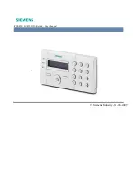
RiteKey 30-01
(IP65 Rating Keypad Face Only)
Contents
Installing Keypad and Backplate ...............................................................
page
1-3
Wiring Details..................................................................................................
page
4
User Manual.................................................................................................
page
5-6
Adams Rite Europe Ltd, Moreton Industrial Estate, London Road, Swanley, Kent, UK, BR8 8TZ
Tel: +44 (0)1322 668024 Fax: +44 (0)1322 660996 E-mail: [email protected] www.adamsrite.co.uk