


JABLOTRON
ALARMS
a.s.
Pod
Skalkou
4567/33
46601
Jablonec
n.
Nisou
Czech
Republic
www
.jablotron.com
||
|
JA-150E Wireless keypad
JA-10E BUS keypad
1 / 3
MLU25301
The keypad is a component of the
JABLOTRON 100
system used
to control the control panel and display its current status. Using an external
input a door detector can be connected to the keypad
.
It is necessary to use this manual in combination with
the
JABLOTRON 100
installation and user manuals.
The keypad contains 4 function buttons (5), an LCD display (3),
a system indicator (2), status indicators A, B, C, D (1), a keypad with
an RFID chip card/tag reader (4).
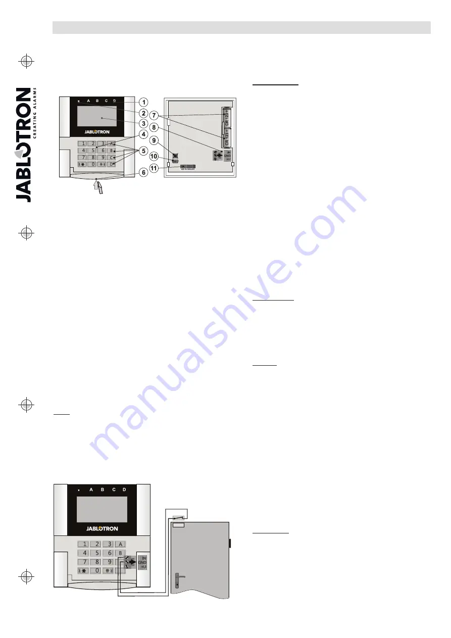
Figure 1: 1 – status indicators A,B,C,D; 2 – system indicator; 3 – LCD
display; 4 – keypad and the RFID reader; 5 – function buttons A, B, C, D;
6 – keypad opening tab; 7 – batteries; 8 – detachable BUS terminals;
9 – tamper contact; 10 – mini USB connector; 11 – production number.
Installation
1. Open the keypad housing
by pressing the tab on the bottom (6)
using a screwdriver which will release the keypad from its back part.
2.
Screw the back part on a selected place. We recommend using all
four mounting holes and screws to attach the plastic base.
To meet the criteria of EN 50131 grade 2 the plastic base must
be screwed by at least two screws using the mounting hole next
to the tamper contact hole and the mounting hole in the diagonal
corner.
3. Insert two CR123A lithium batteries in the keypad.
4. Insert the keypad back into the back part and lock the bottom tab
using the little screw.
5. Proceed according to the control panel installation manual.
Basic procedure:
a. The JA-111R radio module must be installed in the control
panel. The keypad must be in its communication range.
b. When the device is switched on, the system indicator (2) will
start showing yellow light to indicate that the keypad has not yet
been enrolled to the system.
c. Open
the
F-Link
software, select the required position in the
Devices
window, and click on the
Enroll
button which will open
the enrollment mode.
d. Press the keypad cover to enroll the keypad and the yellow
LED indicator starts flashing (twice with pause) to indicate
Service mode, which may take a few seconds. The enrollment
signal can be sent by inserting the batteries in the keypad
or pressing the tamper contact.
Notes:
Enrollment is also possible by entering its production code (11)
in the F-Link software or using a bar code scanner. All numbers
stated under the bar code must be entered (e.g. 1400-00-0000-
0001).
Installation of a magnetic contact
The keypad supports connection of a door detector. The IN input
reacts to being disconnected from the common GND contact.
The control panel’s reaction to an activated IN input is configurable
in the F-Link SW.
Figure 2: connecting a magnetic contact
Setting the properties
Go to the
Devices
window in the F-Link software. When you are
at the keypad position, click on the
Internal settings
option which will
display a dialogue window to configure its settings and function buttons.
Internal settings are separated into 2 basic tabs:
Function
and
Settings
.
The Function tab:
Time
– Displays the current time in the top-right corner of the display
User text
– Enables showing any text, for example the phone number
of an installer company, etc.
Temperature
– Displays the temperature measured by one
of the selected thermometers in the bottom-right corner of the keypad
display.
Buttons Function
– On the left is a selection of button functions.
On the right is a selection of Sections or PG outputs to which the functions
will be assigned. A function button can be assigned with these functions:
None, Set/Unset, Unset/Partially set, Unset/Partially set/Set, Section
indication, Panic, Fire, Audible panic, Medical Troubles, PG ON/OFF, PG
ON, PG OFF, PG indication, PG indicates inversely, Common function
button.
Authorization
– Setting and Unsetting requires user authorization.
When this parameter is disabled the function buttons can be operated
without authorization, however this does not apply to Unsetting a section
which always requires authorization. Both ON and OFF statuses
of PG outputs can be configured to be operated with or without
authorization.
Import
– Enables copying settings from other keypads of the same type
and FW version, which have already been enrolled. For example, this can
be utilized when the building has multiple entrances and it is necessary for
all keypads to have identical functions. In addition, this function can also
be used when replacing a faulty keypad with another. The Import button
provides the history of keypad settings on a particular position
of the device.
Section selection
– Selection of sections which can be controlled
by authorization (using an RFID chip or a code)
PG selection –
Selection of PG outputs which can be controlled
by authorization (using an RFID chip or a code)
The Setting tab:
Acoustic indication of selected sections:
Higher volume
– Increased volume of indication (it does not apply
to alarm).
Alarms
– Indicates alarm (sounds a siren).
Entrance delay
– Continuous sound during the entrance delay.
Exit delay
– Slow beeping (1x every second)
Exit delay when partially set
– Slow beeping (deactivated by default).
Segment status change
–
Beeps once when a status is changed.
Function:
Optical indication setting:
1.
Indicates permanently
– The keypad indicates permanently.
When the mains electricity is disconnected it indicates the same
way as option 3. When mains electricity is restored the keypad
indicates permanently again.
2.
Section/PG status change on keypad
– The status change
of a section/PG is indicated by a specific function button
and a status indicator. Entrance delay and alarms are indicated
by all function buttons and status indicators.
3.
Section/PG status change on segment
– The keypad indicates
after a change of the section/PG status, entrance delay and alarm
only by a particular button and a section indicator.
4.
Segment status change on keypad
– The keypad indicates
after a change of the section/PG status by a particular button and
a section indicator. Entrance delay and alarms are indicated
acoustically only.
5. Entrance delay/Alarms on segment
– The keypad indicates
entrance delays and alarms with a function button and a status
indicator. Change of section/PG status is not indicated visually
or acoustically.
6.
Wake-up by pressing
– The keypad starts to optically and
acoustically indicate after the front cover has been opened and
also when a key or a function button has been pressed.
RFID reader:
In order to save energy we limit the RFID reader to function for
3 seconds after pressing the keypad cover. The RFID reader can be
also completely disabled. This setting applies to wireless keypads
as long as they are permanently supplied by an external power
supply, otherwise their RFID readers will always turn off automatically.
Permanently ON
–
the RFID reader is always active. This works only
when the
Optical indication setting
is set to the option number
1 - Indicates permanently.
Activated by pressing
– When the keypad is activated the RFID
wakes up for 3 seconds.
Disabled
– RFID reader is permanently disabled.


