FV541 Rev. T 7/18/2018
Page 5
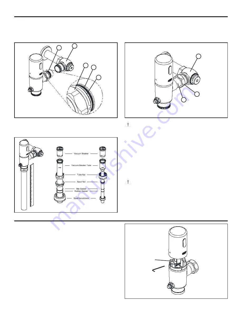
STEP 3.1
Prior to attaching flush valve to control stop(A) inspect and verify
that the O-ring (C) is located within the O-ring groove at the tailpiece.
Ensure the locking nut (D) and locking snap ring (E) are also present
on the tailpiece. See Figure 3.
STEP 3.2
Lubricate O-ring with water if necessary and carefully insert flush
valve tailpiece into the control stop valve to ensure O-ring remains
seated. Tighten locking nut using a smooth jawed wrench. See
Figure 4.
Flush Valve Installation - STEP 3
STEP 3.3
Determine the length of vacuum breaker tube required to join the
flush valve and fixture spud, and cut if necessary. See Figure 5.
Figure 5
Water Closet
Urinal
Remove Sensor Cap (Applies to all versions) - STEP 4
Solenoid
connecting wire
Figure 6
STEP 4.1
Use the 3/32” Allen Wrench to loosen the internal set screw until
it stops. Screw will retract into the base to eliminate loss.
STEP 4.2
Rotate cap clockwise and pull cap up to remove.
STEP 4.3
Disconnect black solenoid plug before accessing batteries.
STEP 3.4
Assemble and secure the vacuum breaker tube assembly and spud
nut assembly to the flush valve and fixture spud by hand tightening
the spud nut and vacuum breaker tube nut.
Adjust and plumb the valve assembly. Tighten all connections with
smooth jawed wrench and turn on water supply at the control stop.
See Figure 5.
DO NOT
use pipe sealant or plumbing grease on any valve
component or coupling with the exception of the Control Stop
Inlet! Ensure Vacuum Breaker does not twist or warp when
tightening Vacuum Breaker Tube Nut.
DO NOT
cut vacuum breaker tube shorter than 6” below
the -C-L- indicator mark, as vacuum breaker must be 6” above
the fixture. Consult plumbing Codes & Regulations for specific
details.
Figure 3
B
A
E
C
D
A
B
D
Figure 4


