background image

Chapter 7 Cable Installation

There are two cable troughs on the two sides of the RC8910A cabinet and PC8910A

cabinet. The cable troughs are used for routing the external cables of the BC8910A cabinet

when two cabinets are stacked.

The PC8910A cabinet provides two cable-through holes at the bottom of the box. The

cable-through holes are used for routing the power cable and monitoring cable of the

PC8910A cabinet.

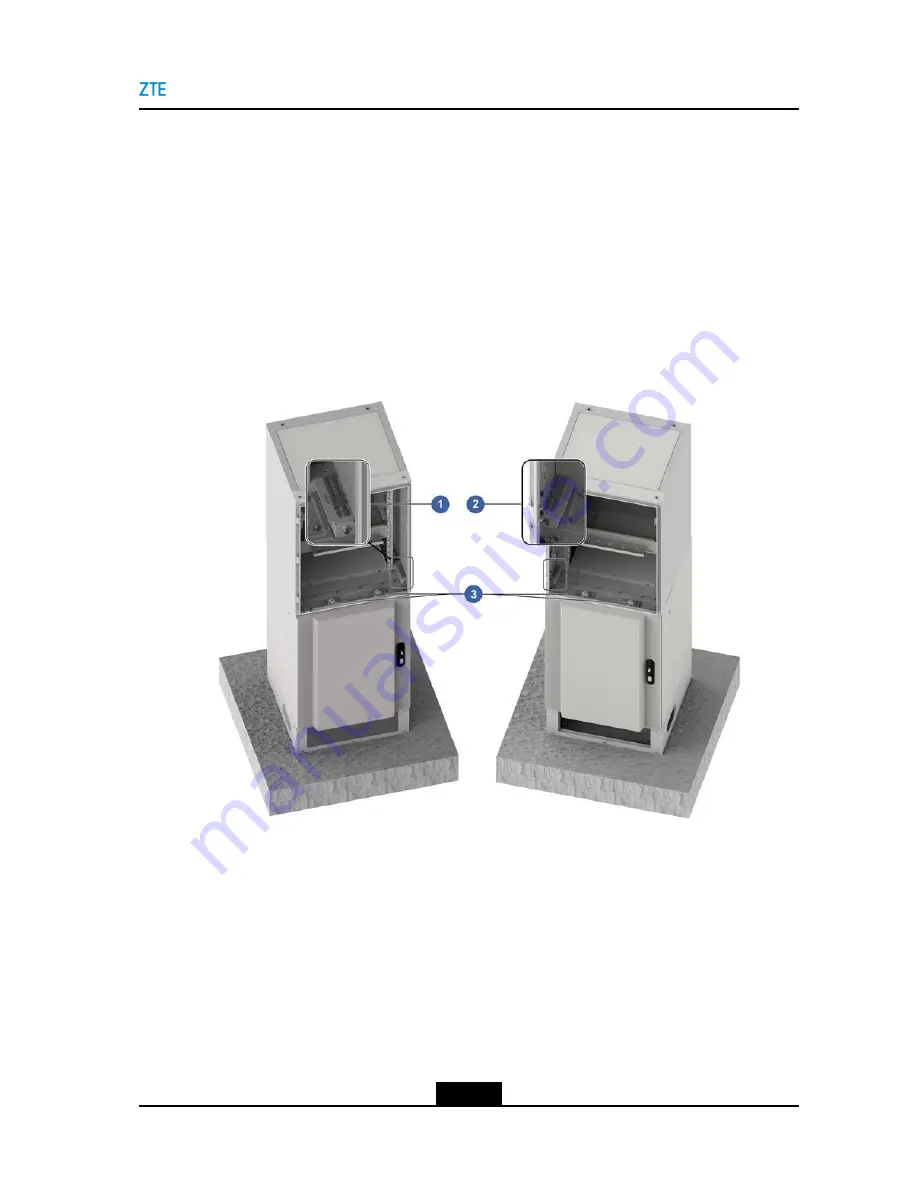
Cable-Through Holes of BC8910A

For the cable-through holes of the BC8910As when being stalled in a stacked manner, see

Figure 7-4

.

Figure 7-4 Cable-Through Hole of the BC8910A

1.

Waterproof module on the
right side

2.

Waterproof module on the
left side

3.

Cable-through hole

Cable-Through Holes of the RC8910A Cabinet

To facilitate the routing of cables when the RF and baseband cabinets are stacked and

installed, two cable-through holes and two routing troughs are designed on the top of the

cabinet. The two routing troughs are located on the left and right sides of the RF cabinet.

They are interoperable with external environment and facilitate the routing of the BC8910A

cabinet. The two cable-through holes are located on the front top of the cabinet to facilitate

the routing between RC8910A and BC8910A cabinets.

7-7

SJ-20150203110107-011|2016-03-23 (R1.1)

ZTE Proprietary and Confidential

Summary of Contents for RSU82 S1900

Page 1: ...RSU82 S1900 Hardware Installation ZTE CORPORATION No 55 Hi tech Road South ShenZhen P R China Postcode 518057 Tel 86 755 26771900 Fax 86 755 26770801 URL http support zte com cn E mail 800 zte com cn ...

Page 2: ...ages resulting from the use of or reliance on the information contained herein ZTE CORPORATION or its licensors may have current or pending intellectual property rights or applications covering the subject matter of this document Except as expressly provided in any written license between ZTE CORPORATION and its licensee the user of this document shall not acquire any license to the subject matter...

Page 3: ...rview 7 1 7 2 Cable Through Holes 7 6 7 3 Waterproof Module Description 7 9 7 3 1 Waterproof Module of the Baseband Cabinet 7 9 7 3 2 Waterproof Module of the RF Cabinet 7 11 7 4 Grounding Cable Installation 7 12 7 4 1 Installing a Grounding Cable for the BC8910A Cabinet 7 13 7 4 2 Installing a Grounding Cable for the RC8910A Cabinet and PC8910A Cabinet 7 16 7 5 Power Cable Installation 7 18 7 5 1...

Page 4: ... 54 7 8 3 Connecting a Battery Temperature Monitoring Cable for the PC8910A Cabinet 7 57 7 8 4 Installing a Door Access Monitoring Cable for the PC8910A Cabinet 7 59 7 8 5 Installing the Water Level Monitoring Cable of a PC8910A Cabinet 7 61 7 9 Waterproof Module Installation 7 63 7 9 1 Installing the Waterproof Module for the BC8910A Cabinet 7 63 7 9 2 Installing the Waterproof Module for the RC8...

Page 5: ...lation Chapter 3 Unpacking and Inspection Describes precautions about equipment unpacking and inspection Chapter 4 Cabinet Installation Describes how to install the cabinet of the ZXSDR BS8900A Chapter 5 Component Installation in a Cabinet Describes how to install the RSU and battery of the ZXSDR BS8900A Chapter 6 Installing the GPS Antenna Optional Describes how to install the GPS antenna on the ...

Page 6: ...tly hazardous situation Failure to comply will result in death or serious personal injury Warning indicates a potentially hazardous situation Failure to comply can result in death or serious personal injury Caution indicates a potentially hazardous situation Failure to comply can result in moderate or minor personal injury Notice indicates equipment or environment safety information Failure to com...

Page 7: ...pter 1 Installation Flow For the installation flow of the ZXSDR BS8900A see Figure 1 1 Figure 1 1 ZXSDR BS8900A Installation Flow 1 1 SJ 20150203110107 011 2016 03 23 R1 1 ZTE Proprietary and Confidential ...

Page 8: ...ZXSDR BS8900A Hardware Installation This page intentionally left blank 1 2 SJ 20150203110107 011 2016 03 23 R1 1 ZTE Proprietary and Confidential ...

Page 9: ...on Table 2 1 Tools and Meters Cate gory Name Example Feeder connector knife 75 Ω coaxial cable stripper Multi functional crimping pliers Multimeter Standing wave ratio tester Special purpose tools Earth resistance tester 2 1 SJ 20150203110107 011 2016 03 23 R1 1 ZTE Proprietary and Confidential ...

Page 10: ...hase sockets and three three phase sockets with the current capacity larger than 15 A Phillips screwdrivers 4 6 and 8 each Flat head screwdrivers 4 6 and 8 each Adjustable wrenches 6 8 10 and 12 each Dual purpose wrenches 17 and 19 each Socket wrenches Paper knife 5 kg claw hammer General purpose tools 2 2 SJ 20150203110107 011 2016 03 23 R1 1 ZTE Proprietary and Confidential ...

Page 11: ... gory Name Example Irons 300 W and 40 W each Inner hexagon wrench Solder wires 50 m 164 feet tape measure 5 m 16 feet steel tape Angle instrument Mea sure ment tools 2 3 SJ 20150203110107 011 2016 03 23 R1 1 ZTE Proprietary and Confidential ...

Page 12: ...ple Compass Level bar Plumb Antistatic wrist strap slip proof gloves Protec tion tools Safety helmet Hacksaw with several saw blades sharp nose pliers 8 diagonal pliers 8 Clamp tools 2 4 SJ 20150203110107 011 2016 03 23 R1 1 ZTE Proprietary and Confidential ...

Page 13: ... gory Name Example round nose pliers 8 Pincer pliers 8 Needle files medium sized Nippers Paint brush Scissors Air heater Solder removal tool Hydraulic crimper Crowbar 2 5 SJ 20150203110107 011 2016 03 23 R1 1 ZTE Proprietary and Confidential ...

Page 14: ...rum analyzer required in certain special cases BTS tester Meters Field strength tester required in certain special cases Table of Contents Technical Documents 2 7 Precautions for cabinet transport 2 7 Installation Precautions 2 7 2 6 SJ 20150203110107 011 2016 03 23 R1 1 ZTE Proprietary and Confidential ...

Page 15: ...due to environment restrictions cushioning materials such as foamed plastic and paperboard must be used to protect the cabinet from scratches 2 3 Installation Precautions The following precautions should be abided by during the installation l The ZXSDR BS8900A hardware installation personnel must participate in the training related to communication equipment installation to master installation ski...

Page 16: ...ware Installation l The equipment must be powered on within 24 hours after the package is opened Power off cannot exceed 24 hours in maintenance 2 8 SJ 20150203110107 011 2016 03 23 R1 1 ZTE Proprietary and Confidential ...

Page 17: ... or stains l Verify that the accessories required for the installation are correct and complete Equipment Handover After the examination of goods the engineering supervisor and the operator s representative should sign the Unpacking Acceptance Report The Unpacking Acceptance Report is made in duplicate and kept by both parties The engineering supervisor must send the Unpacking Acceptance Report ba...

Page 18: ...ZXSDR BS8900A Hardware Installation This page intentionally left blank 3 2 SJ 20150203110107 011 2016 03 23 R1 1 ZTE Proprietary and Confidential ...

Page 19: ...et RC cabinet and battery cabinet PC cabinet These cabinets can be stacked or installed side by side The lower layer cabinet in the stacked cabinet installation mode is RC8910A or PC8910A The upper layer cabinet in the stacked cabinet installation mode is BC8910A The base does not accompany the delivery of these cabinets The base needs to be installed before the floor mounted cabinet installation ...

Page 20: ... cabinet on its top the floor mounted cabinet needs to be installed with the top cover Flow for Stacking Cabinets In the stacked cabinet installation you just need to stack another cabinet onto the top of the floor mounted cabinet For the installation flow see Figure 4 2 4 2 SJ 20150203110107 011 2016 03 23 R1 1 ZTE Proprietary and Confidential ...

Page 21: ...cabinet together with the PC8910A cabinet and installing single BC8910A cabinet The installation of the BC8910A cabinet or PC8910A cabinet on the floor is slightly different from that of a RC8910A cabinet No clamping component is required for the installation of the BC8910A cabinet or PC8910A cabinet Context Stabilizing the wind proof pole Use the wind proof pole to stabilize the cabinet door when...

Page 22: ...heat dissipation and easy operation 2 Concrete Platform Description A concrete platform needs to be set up before the cabinet installation The cabinet is installed onto the platform and particular operation space is reserved Do not directly install the expansion bolts on the roof The dimensions of the concrete platform are as follows l Stacked cabinets The space must be greater than 1600 mm x 1500...

Page 23: ... Stacked Cabinets l Side by side installed cabinets The space must be greater than 2200 mm x 1500 mm in such a scenario see Figure 4 5 Figure 4 5 Concrete Base Size Requirement For Side by Side Cabinets 4 5 SJ 20150203110107 011 2016 03 23 R1 1 ZTE Proprietary and Confidential ...

Page 24: ...e or the dimensions in Figure 4 6 determine the holes for expansion bolts used for securing the cabinet base Figure 4 6 Dimensions of the Base and Expansion Bolt Positions 4 Drill holes and install the expansion bolts For an overview of an expansion bolt see Figure 4 7 For how to drill holes and install the expansion bolts refer to Table 4 1 4 6 SJ 20150203110107 011 2016 03 23 R1 1 ZTE Proprietar...

Page 25: ...ng hole drilling see Figure 4 8 2 Screw a bolt clockwise slightly until the guide rib at the bottom of the expansion bolt cannot quit from the guide slot Put the expansion bolt into the installation hole vertically and knock the expansion bolt with a claw hammer until the top of the bolt aligns with the ground see Figure 4 9 3 Fasten the expansion bolt clockwise and ensure that the bolt is fixed t...

Page 26: ...ZXSDR BS8900A Hardware Installation Figure 4 8 Installing an Expansion Bolt 1 Figure 4 9 Installing an Expansion Bolt 2 4 8 SJ 20150203110107 011 2016 03 23 R1 1 ZTE Proprietary and Confidential ...

Page 27: ...at the installation position of the base is correct pass the expansion bolts through the spring washers flat washers and base in turn and then screw the bolts into the expansion tubes clockwise to make them fully expanded in the ground see Figure 4 11 Figure 4 11 Fixing the Base 4 9 SJ 20150203110107 011 2016 03 23 R1 1 ZTE Proprietary and Confidential ...

Page 28: ...tall the clamping components Use two M6 hexagonal screws to fasten the clamping components to the corresponding installation holes of the rear side of the base see Figure 4 12 Figure 4 12 Installing the Clamping Component Note Ensure that the clamping components are vertical to the base Otherwise the cabinet installation may be difficult b Place the cabinet onto the base see Figure 4 13 4 10 SJ 20...

Page 29: ...se c Steadily push the cabinet backwards until the clamping components are fully inserted in the holes on the rear side of the cabinet and the cabinet is aligned with the base edges see Figure 4 14 4 11 SJ 20150203110107 011 2016 03 23 R1 1 ZTE Proprietary and Confidential ...

Page 30: ... the cabinet steadily so as to prevent the cabinet from falling down d Use two M12 hexagonal screws with rubber washers at the both sides of the front of the cabinet to secure the cabinet to the base see Figure 4 15 4 12 SJ 20150203110107 011 2016 03 23 R1 1 ZTE Proprietary and Confidential ...

Page 31: ...10A cabinet or PC8910A cabinet on the base a Place the cabinet on the base b Secure the cabinet to the base by using four M12 hexagonal screws with rubber washers at each bottom corner of the cabinet see Figure 4 16 4 13 SJ 20150203110107 011 2016 03 23 R1 1 ZTE Proprietary and Confidential ...

Page 32: ...low place or adjusting the tilt to make the vertical tilt of no more than 5 10 Verify the installation Check the cabinet installation position and cabinet tilt after fastening screws tightly The vertical gradient cannot be greater than 5 11 Optional Install a top cover It is required to install a top cover on the top of the floor mounted cabinet or the upper cabinet of the stacked cabinets Place t...

Page 33: ...using a special wrench and remove the air filter see Figure 4 18 To route cables the front panel of the cabinet bottom and the air filter must be removed After all the cables of the ZXSDR BS8900A are installed you must install the air filter and the front panel of the cabinet bottom 4 15 SJ 20150203110107 011 2016 03 23 R1 1 ZTE Proprietary and Confidential ...

Page 34: ...talled Context The common combination modes of the ZXSDR BS8900A cabinets are described as follows l Combination 1 BC8910A RC8910A PC8910A l Combination 2 BC8910A RC8910A In these two combinations BC8910A is the cabinet that needs to be stacked Steps 1 Place the top cover on the top of the upper layer cabinet and fix it to the cabinet using four M12 hexagon bolts with steel gaskets 4 16 SJ 2015020...

Page 35: ...y removing the screws see Figure 4 19 Figure 4 19 Removing the Screws from the Cover Plate of the Cable Trough 3 Remove the cover plate of the routing hole by removing the four screws inside the lower layer cabinet see Figure 4 20 4 17 SJ 20150203110107 011 2016 03 23 R1 1 ZTE Proprietary and Confidential ...

Page 36: ...m the Cover Plate of the Routing Hole 4 Insert four M12 bolts with rubber washers through the holes at the four corners of the upper layer and low layer cabinets to fix the cabinets see Figure 4 21 4 18 SJ 20150203110107 011 2016 03 23 R1 1 ZTE Proprietary and Confidential ...

Page 37: ...inet the heater will cover the M12 bolt installation holes at the rear of the cabinet You need to remove the locking screws of the heater first and then pull out the heater partially before installing M12 bolts The power cable of the heater is not required to be removed 4 19 SJ 20150203110107 011 2016 03 23 R1 1 ZTE Proprietary and Confidential ...

Page 38: ...f the upper layer cabinet see Figure 4 22 Figure 4 22 Removing the Cover Plate of the Routing Hole 6 Secure the routing hole components beneath the cabinet routing hole on the top of the lower layer cabinet see Figure 4 23 4 20 SJ 20150203110107 011 2016 03 23 R1 1 ZTE Proprietary and Confidential ...

Page 39: ...g the Cable Through Components of the Lower Layer Cabinet 7 Secure the routing components onto the cabinet routing hole at the bottom of the upper layer cabinet see Figure 4 24 4 21 SJ 20150203110107 011 2016 03 23 R1 1 ZTE Proprietary and Confidential ...

Page 40: ...adjust the cabinet position and gradient 9 Seal the apertures by using seamgum There are apertures between the upper and lower cabinets after the cabinets are installed in stack mode which may cause water logging and equipment corrosion You need to seal the apertures by using seamgum after the cabinets are installed in stack mode a Seal the apertures evenly by using seamgum see Figure 4 25 4 22 SJ...

Page 41: ...tacked Cabinets by Using Seamgum The cable troughs on the left and right sides of the lower cabinet are not required to be sealed b Remove the overflowing seamgum by using cloth End of Steps 4 23 SJ 20150203110107 011 2016 03 23 R1 1 ZTE Proprietary and Confidential ...

Page 42: ...ZXSDR BS8900A Hardware Installation This page intentionally left blank 4 24 SJ 20150203110107 011 2016 03 23 R1 1 ZTE Proprietary and Confidential ...

Page 43: ... frequency two transmit links are in the same boot section and use different carrier frequencies the antenna jumper wires can only connect to the ANT1 and ANT3 ports Prerequisite You wore an ESD wrist strap Steps 1 Determine the target slot to install the RSU hold the handle of the RSU with one hand support the bottom of the RSU with the other hand try to make parallel the module and the guiding p...

Page 44: ...cable from the PDM to the POWER port of the RSU module End of Steps 5 2 Installing Batteries This procedure describes how to install batteries in the PC8910A cabinet Caution If only four batteries are used the unconnected terminals for batteries must be wrapped up with insulation materials 5 2 SJ 20150203110107 011 2016 03 23 R1 1 ZTE Proprietary and Confidential ...

Page 45: ... PC8910A cabinet can be configured with two packs of batteries and each battery pack has four 12 V batteries in serial connection Refer to the followings to ensure that the dimensions and weight of the selected batteries are applicable to the PC8910A cabinet before these batteries are installed into the PC8910A cabinet l Every battery rack supports 260 kg at most meaning that each battery is 65 kg...

Page 46: ...the Battery Pack and the Inner Wall of the PC8910A Cabinet Item Stated Spacing Actual Spacing Battery Spacing 2 mm Spacing between the leftmost rightmost battery and the PC8910A cabinet W1 9 mm Spacing between the battery top and the PC8910A cabinet H1 12 mm Spacing between the battery back and the PC8910A cabinet D1 12 mm Steps 1 Use the multimeter to verify that each battery is functioning prope...

Page 47: ... PC8910A cabinet for electrical safety so as to avoid short circuits or even fire caused by wiring terminals touching with the inner wall 3 Connect the terminals of the batteries 4 Check the installation against the checklist shown in Table 5 2 and ensure that the answer to each item is Yes Table 5 2 Installation Verification Checklist SN Check Criterion Check Result 1 The installed cabinet stands...

Page 48: ...ZXSDR BS8900A Hardware Installation This page intentionally left blank 5 6 SJ 20150203110107 011 2016 03 23 R1 1 ZTE Proprietary and Confidential ...

Page 49: ...y of installing the GPS antenna and cables and to save installation space and time Context To install the GPS antenna on the top of the cabinet you need to install GPS installation assembly on the hanger on the top of the cabinet For GPS installation assemble see Figure 6 1 Figure 6 1 GPS Installation Assembly 1 GPS antenna 2 GPS installation clamp 3 GPS cable trough 4 GPS installation accessory 6...

Page 50: ...tallation accessory see Figure 6 2 Note The GPS cable trough is fixed to the GPS installation accessory to bind the GPS cable Figure 6 2 Fixing the GPS Accessory on the Top of the Cabinet 2 Use a GPS clamp to fix the GPS antenna and use two bolts to fix the GPS clamp on the GPS installation accessory see Figure 6 3 6 2 SJ 20150203110107 011 2016 03 23 R1 1 ZTE Proprietary and Confidential ...

Page 51: ...e 6 3 Fixing the GPS Antenna End of Steps Result For the installed GPS antenna on the top of the cabinet see Figure 6 4 Figure 6 4 GPS Antenna Installed on the Top of the Cabinet 6 3 SJ 20150203110107 011 2016 03 23 R1 1 ZTE Proprietary and Confidential ...

Page 52: ...ZXSDR BS8900A Hardware Installation This page intentionally left blank 6 4 SJ 20150203110107 011 2016 03 23 R1 1 ZTE Proprietary and Confidential ...

Page 53: ...le Installation 7 40 Monitoring Cable Installation 7 50 Waterproof Module Installation 7 63 Installing the Air Filter 7 64 7 1 Cabling Overview External Cables of Stacked Cabinets The external cables are used to connect the BC8910A cabinet and RC8910A cabinet to external devices The external cables are routed into the BC8910A cabinet or RC8910A cabinet through the waterproof module at the bottom o...

Page 54: ... Cable Routing of the BC Cabinet For stacked cables the external cables of the BC8910A cables are threaded through the waterproof modules on two sides of the BC8910A cabinet and then routed along the cable troughs of the RC8910A cabinet For external cable routing of the BC8910A cabinet see Figure 7 1 7 2 SJ 20150203110107 011 2016 03 23 R1 1 ZTE Proprietary and Confidential ...

Page 55: ...RC Cabinet The external cables of the RC8910A cabinet include l Antenna jumper l AISG cable External Cable Routing of the RC Cabinet The jumper wires are threaded though the waterproof module at the bottom of the cabinet see Figure 7 2 7 3 SJ 20150203110107 011 2016 03 23 R1 1 ZTE Proprietary and Confidential ...

Page 56: ...o the RC cabinet The inter cabinet cables include l Grounding cable of the RC cabinet l DC power input cable of the RC cabinet l SFP cable The inter cabinet cables are threaded through the cable through holes on the BC8910A cabinet and RC8910A cabinet and then connected to the corresponding ports see Figure 7 3 7 4 SJ 20150203110107 011 2016 03 23 R1 1 ZTE Proprietary and Confidential ...

Page 57: ... cables and feeders are routed in parallel along a cable ladder ensure that a spacing greater than 100 mm is reserved between different types of cables l If signal cables and power cables need to be laid out in a cross manner the cross angle must be 90 l If a cable needs to bend ensure that the bending radius meets the minimum bending radius requirement meaning that the bending radius must be equa...

Page 58: ...Requirements of Bending Radius of Feeders Minimum Bending Radius Recommended Feeder Type Single Bending Continuous Bending 15 times Soft 1 2 feeder 150 mm 300 mm 1 2 feeder 500 mm 1250 mm 7 8 feeder 900 mm 2500 mm 5 4 feeder 1500 mm 3800 mm Cable Bundle Requirements l The cable ties must be at an even spacing with enough slack and face the same direction l The surplus part of cable clips should be...

Page 59: ...7 4 Cable Through Hole of the BC8910A 1 Waterproof module on the right side 2 Waterproof module on the left side 3 Cable through hole Cable Through Holes of the RC8910A Cabinet To facilitate the routing of cables when the RF and baseband cabinets are stacked and installed two cable through holes and two routing troughs are designed on the top of the cabinet The two routing troughs are located on t...

Page 60: ... Cable Tray l Before the stacked installation the waterproof plates for the two cable through holes must be removed and then reseated after cables are routed Cable Through Holes of the PC8910A Cabinet Two cable through holes right and left are designed on the bottom of the PC8910A cabinet and the two holes are protected with waterproof plugs Remove these plugs before the cables are routed and rese...

Page 61: ...the cabinet If batteries are installed in the lower cabinet an acid gas prevention module must be installed Note If there are too external cables in the baseband cabinet to be routed through the cable through hole reserved by the waterproof module the waterproof should be removed You can route the cables through the cable tray directly and fill the gaps with fireproof clay For the structure of the...

Page 62: ...itoring cables such as temperature monitoring cables door access control cables fan power cables of the PC cabinet and dry contact cables J 2 9 5 For DC input power cables grounding cables battery power cables GPS cables and E1 75 120Ω trunking cables Waterproof on the right side V 4 17 For RRU power cables Cable Routing Example For cables routed through the waterproof module of the baseband cabin...

Page 63: ...tructure of the waterproof module at the bottom of the RF cabinet see Figure 7 8 Figure 7 8 Waterproof Module of the RF Cabinet Table 7 3 Descriptions for Holes on the Waterproof Module Hole Quantity Diameter mm Function F 9 6 5 For optical fibers and AISG cables P 3 9 For power cables R 12 12 5 For antenna cables 7 11 SJ 20150203110107 011 2016 03 23 R1 1 ZTE Proprietary and Confidential ...

Page 64: ...of module of the RF cabinet see Figure 7 10 Figure 7 10 Cable Routing Through the Waterproof Module of the RF Cabinet 1 Optical fibers 2 Power cables 3 Antenna cables 7 4 Grounding Cable Installation The grounding cable installation includes installation of the grounding cables of stacked cabinets and single cabinet This procedure describes how to install the grounding cables for stacked cabinets ...

Page 65: ...alling a Grounding Cable for the BC8910A Cabinet This procedure describes how to install the bus grounding cable of the stacked cabinets The bus grounding cable is connected to a nearby outdoor grounding busbar Prerequisite l The ESD wrist strap must be worn l The tributary output of the power supply is cut off 7 13 SJ 20150203110107 011 2016 03 23 R1 1 ZTE Proprietary and Confidential ...

Page 66: ...es are securely fixed Steps 1 Remove the cover of the left side routing trough and the front baffle of the base 2 Route the grounding cable along the left side waterproof module of the baseband cabinet and the left side routing trough of the RF cabinet and connect the cable to the grounding copper bar of the baseband cabinet see Figure 7 12 Prepare the grounding cable of a particular length in acc...

Page 67: ...ble 3 Secure one end of the grounding cable to the ground copper bar of the left side of the BC8910A cabinet see Figure 7 12 4 Connect the other end of the grounding cable to the outdoor grounding copper bar 5 Bundle and fasten the grounding cable along the side wall of the cabinet End of Steps 7 15 SJ 20150203110107 011 2016 03 23 R1 1 ZTE Proprietary and Confidential ...

Page 68: ...D wrist strap must be worn l The tributary output of the power supply is cut off Steps Installing the grounding cable of stacked cabinets 1 Prepare the grounding cable of a particular length in accordance with the distance between the BC8910A cabinet and the grounding copper bar Note A redundant length must be reserved when you prepare the grounding cable 2 Remove the screw configured for the grou...

Page 69: ...nce with the distance between the PC8910A cabinet and the outdoor grounding copper busbar 6 Remove the screw on the grounding nut of the PC8910A cabinet and secure one end of the grounding cable to the cabinet 7 Thread the grounding cable though the cable through hole at the bottom of the cabinet route the cable to the outdoor grounding copper busbar and then secure the other end of the cable to t...

Page 70: ... of the BC8910A cabinet converted to be DC power in the PDM and then distributed to other cabinets For the AC power distribution of the ZXSDR BS8900A cabinets see Figure 7 14 Figure 7 14 shows the power distribution from the BC8910A cabinet to the RC8910A and PC8910A cabinets when the B121 PDM is installed When installing the ZXSDR BS8900A cabinets you need to connect the corresponding power cable...

Page 71: ...the B201 PDM is installed The way to connect the cable of the B121 PDM is similar to that of the B201 PDM Figure 7 15 AC Power Distribution of the ZXSDR BS8900A Cabinets 2 The BC cabinet supports single phase and three phase AC input The connected terminals of single phase and three phase AC power are different l Three phase AC power input cable For the connectors of the three phase AC power input...

Page 72: ...er input cable For the connectors of the single phase AC power input cable see Figure 7 17 Figure 7 17 Connectors of the Single Phase AC Power Input Cable Table 7 5 Chromatograph Descriptions of the Single phase AC Power Input Cable Pin Signal Definition Signal Description Color End A End B 1 L L phase wire Red 2 N AC neutral wire Blue 3 PE Protective ground Yel low green AC power input terminal o...

Reviews: