4
Actuators
MOA OC are standardly delivered with one-cable gland P36
(for cable diameter 20–25 mm).
Variation with
trhee-cable input M25x1,5 is necessary to mention in order.
3. TECHNICAL PARAMETERS
Main technical characteristics are listed in the table.
Electric motor supply voltage
3 x 400
(380)
V / 50 Hz
(or as indicated on the label)
Degree of protection
IP 67
Other technical parameters are listed in the Technical Conditions.
4. OPERATING POSITION
Operating position
MODACT MOA OC actuators is optional if the electric motor is not under the actuator, i.e.
the electric motor axis is not lower than 15 degrees below the horizontal level.
5. DESCRIPTION
The actuators are designed for direct mounting to the valve. The connection is made via a flange with B3 shape
according to ISO 5210
(Shape E according to DIN 3210),
shape C according to DIN 3338. The arrangement of parts is
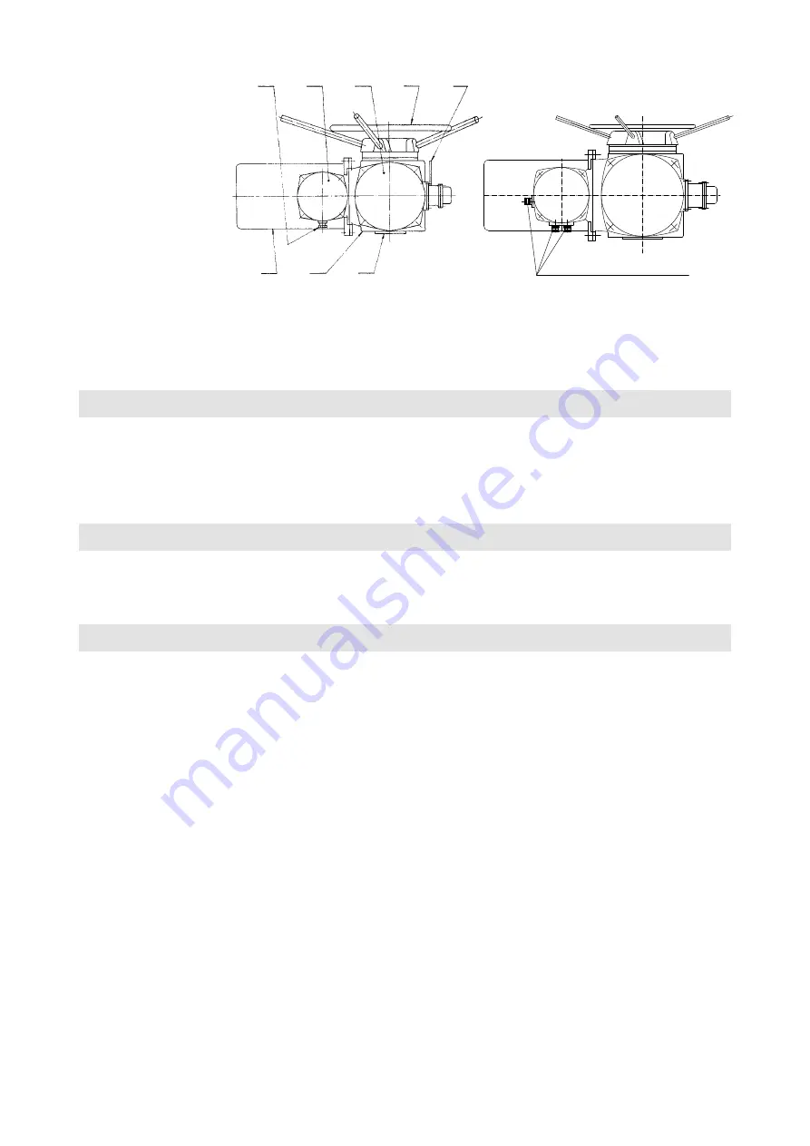
shown in Fig 1. The three-phase asynchronous electric motor 1 drives a worm wheel via a countershaft gear, which
is coupled to the output shaft of the actuator 8 through a switching clutch. Thereby the motor control transmits motion from
the electric motor to the output shaft. The countershaft gear, worm, worm wheel, switching clutch and the output shaft are
placed in the power cabinet 2. The switching clutch is provided with control lever 3 located outside on the side of the power
cabinet, which also allows connecting the output shaft with the hand wheel 4 and thus manual control. In manual control it
is necessary to push the control lever according to the instructions. Turning the hand wheel clockwise closes the valve.
After the start-up of the electric motor the control lever and thus the clutch automatically return to the motor control
position. To allow tripping of the electric motor upon reaching the desired torque on the output shaft, the worm is axially
movable and axially sprung in both directions of movement. Its shifting distance then depends on the torque of the output
shaft and the characteristics of the springs. The movement of the worm, which is then a measure of the torque at the output
shaft, is transmitted to the control cabinet, where it is used for switching of the torque switches.
The output shaft is connected by means of the transmission gear with the units of positional and signalling switches,
thereby enabling the electric motor to trip after reaching the desired position of the output shaft and remote indication of
its position. All operating units, i.e. the torque control unit, position switching unit and signalling unit are located in the
control cabinet 5. The contacts of theirs micro switches are completely interconnected with the actuator terminal board,
which is located in the terminal box 6. This terminal board is also connected to the terminals from the electric motor
(electric motor does not have its own terminal board).
The terminal box has one cable gland P 36
(7),
which allows the sealing of the connection cable for connecting control
and signalling circuits, and electric motor power supply.
The individual control units consist of mechanical drives and dedicated micro switches. They are positioned on
a common control board
(Fig. 2).
Fig. 1 –
Actuator assembly
3x KABELOVÁ VÝVODKA M25x1,5
Ø kabelu 9 - 16 mm
3x cable gland M25x1.5
of cable ø 9–16 mm
Legend:
1 – Three-phase asynchronous
electric motor
2 – Power cabinet
3 – Clutch control lever
4 – Hand wheel
5 – Control box
6 – Terminal box
7 – P 36 cable outlet
(cable ø 20–25 mm)
8 – Output shaft
7
1
2
8
6
5
4
3


