4
5. DESCRIPTION
The
MODACT MOA aactuators are designed to be mounted directly on a valve with the attachment via a flange per
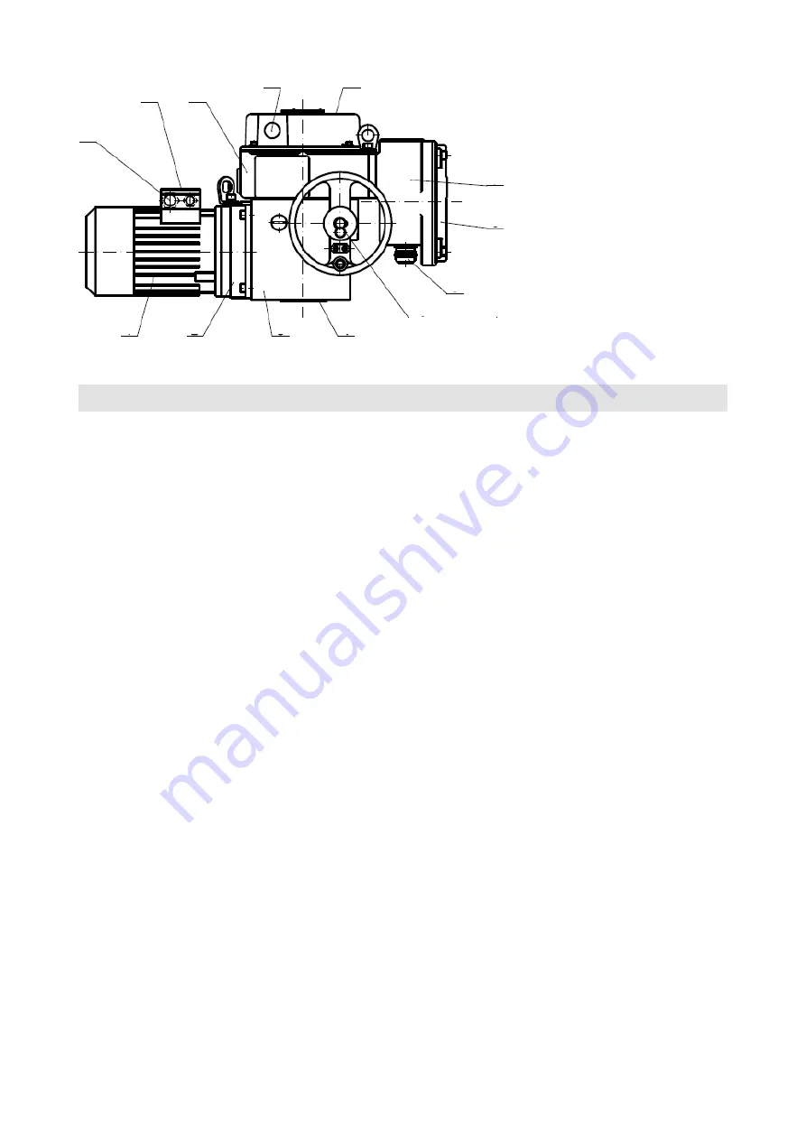
ISO 5210 and a C/E-shaped coupling in accordance with DIN 3210. Arrangement of a part of the actuator is shown in
Figure 1. Using a counter-gear 2 the three-phase asynchronous motor 1 drives the central wheel of the differential gear
installed in the actuator support box
(power gear)
3. During the motorized operation the planet differential crown gear is
held in its invariable position by a self-locking worm gearing. Hand wheel 4, attached to the worm, makes it possible to
operate the actuator manually while the motor is running. The hollow output shaft is fixed to the planet gear driver. The
output shaft reaches to the control box 5 where all the actuator controls are gathered – positional, signalling, and torque
switches, resistance or current transmitter, and heating resistor. Operation of position and signalling switches is derived,
through mechanisms, from the output shaft rotation.
The operation of torque switches is derived from the axial displacement of the
“floating worm”
of manual control, which
is sensed and transferred to the control box by a handle. Control elements are accessible upon removal of cover 6 of this
box. The terminal board box 7 is also hidden under the lid 8. The cable inlets are secured using the cable bushings
(9).
Electric motor is fitted with a separate terminal board 10 and a cable bushing. Output shaft position can be identified on
position indicator 11.
The actuator's various operational functions such as tripping by torque, tripping by position, signalling, remote position
reporting
(resistance or current transmitter)
are provided by mechanical groups
(units).
These are located on the control
board
(Figure 2),
fitted inside the control box.
Control units are differentiated by function as follows:
a) torque tripping unit
12
b) signalling unit
13
c) transmitter setting mechanism
14
d) resistance transmitter with mechanical position indicator
15
e) position unit
16
f) heating element
17
The above units are universal, applicable to the
MODACT MOA actuators of all sizes.
Important notice
Micro switches applied in the various units do not allow two voltages with varying values or phases to be connected to the
contacts of one micro switch. These micro switches can only be used as switches, interrupters or selectors for one circuit.
Description and function of control units
a) The torque tripping unit
(Figure 3)
as an independent assembly unit, it consists of base plate 19, which carried micro
switches 20 and at the same time creates bearings for torque control shaft 22 and locking shaft 29.
Torque control shaft transfers motion of the floating worm from power gear, using segments 23 or 24 and handles 45
or 46, to micro switches MZ or MO. Tripping torque value is adjusted by rotating the segments against the tripping handles.
For possible tripping torque set-up outside the manufacturing plant, segments 23 are provided with a scale providing
individually for each actuator indications of points for setting up the maximum and minimum torque. The torque setting is
Fig. 1 –
Actuator assembly
Explanatory notes:
1 – Three-phase asynchronous
electric motor
2 – Counter gear set box
3 – Power gear
4 – Hand control wheel
5 – Control box
6 – Control box cover
7 – Terminal box
8 – Terminal box cover
9 – Cable bushings
10 – Electric motor terminal board
11 – Position indicator
12 – Cable bushing
12
10
5
11
6
7
8
9
4
3
2
1
Locking screw
of the handwheel


