background image


7    

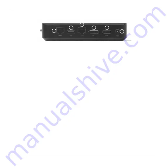
Rear view

Refer to the diagram below to identify the components on the back of the system.

1. Ethernet ports

The eight-pin RJ-45 LAN port supports standard Ethernet cable for connections to  local area 

networks (LAN) with speeds of 10/100/1000Mbps.

2. USB 3.1 port

The USB 3.1 port supports the SuperSpeed USB 3.1 devices and is backwards compatible 

with USB 3.0/2.0/1.1 devices. Use this port for USB 3.1 devices for maximum performance 

with USB 3.1 compatible devices.

3. DisplayPort

DisplayPort supports external connection up to DP1.2, max resolution 4096x2160 @60Hz.

4. HDMI port

The HDMI (High Definition Multimedia Interface) port supports with HDMI2.0, max resolution 

4096x2160 @60Hz.

5. Power input (DC19V)

The supplied power adapter converts AC power to DC power for use with this jack. Power 

supplied through this jack supplies power to the PC. To prevent damage to the PC, always 

use the supplied power adapter.


The power adapter may become warm to hot when in use. Do not cover the adapter and keep it away from your body.

1

2

3

4

5

1

Summary of Contents for ZBOX PRO ZP-CI342

Page 1: ......

Page 2: ...written permission of ZOTAC Products and corporate names mentioned in this manual may be registered trademarks or copyrights of their respective companies and are used for identification purposes only...

Page 3: ...42 9 Installing a memory module 10 Removing the memory module 11 Installing M 2 SSD 2242 2280 module 12 Setting up your ZP CI342 14 Positioning the ZP CI342 16 Mounting the ZP CI342 to an LCD monitor...

Page 4: ...Type C port Audio 1x 3 5mm stereo out microphone combo Storage 1x 2242 2280 M 2 x2 lane NVMe SSD MicroSD microSDHC microSDXC card reader slot Network 2x Gigabit Ethernet LAN Supports Wake on LAN WiFi...

Page 5: ...objects of any kind into the ventilation openings Use this product in environments with ambient temperature on below conditions Main unit 20 C 45 C AC adapter 0 C 40 C Do not walk on the power cord o...

Page 6: ...ackage contents of your new ZP CI342 If any of the below items are damaged or missing contact your retailer Package contents 1 x ZP CI342 1 x L mount kit with 4 screws 1 x VESA mount kit 1 x AC Adapte...

Page 7: ...The type C USB 3 1 port supports the SuperSpeed USB 3 1 devices Use this port for USB 3 1 devices for maximum performance with USB 3 1 compatible devices 5 USB 3 1 port The USB 3 1 port supports the...

Page 8: ...maximum performance with USB 3 1 compatible devices 3 DisplayPort DisplayPort supports external connection up to DP1 2 max resolution 4096x2160 60Hz 4 HDMI port The HDMI High Definition Multimedia In...

Page 9: ...8 Right view Refer to the diagram below to identify the components on the right of the system 1 WiFi antenna connectors The WiFi antenna connector supports the included WiFi antenna 1 1...

Page 10: ...Customizing the ZP CI342 Before installing hardware please follow the instructions below to remove the cover of your ZP CI342 1 Loosen the 4 screws securing the bottom cover 2 Remove the bottom cover...

Page 11: ...the slot at a 45 degree angle 2 Gently press down on the memory module until it locks into place by the arms of the memory slot Note This ZP CI342 accomodates two DDR4 SO DIMM memory modules You must...

Page 12: ...he memory module 1 Locate the SO DIMM memory slot and gently press the two arms securing the memory module outwards as shown in the image below to release the memory module 2 Remove the memory module...

Page 13: ...Locate the M 2 SSD slot and remove the screw 2 Insert an M 2 SATA SSD module into the slot at a 45 degree angle 3 Attach the screw to the M 2 SATA SSD module as shown below M 2 SATA SSD 2242 M 2 SATA...

Page 14: ...13 4 Gently press down on the M 2 SATA SSD module and install the screw on board M 2 SATA SSD 2242 M 2 SATA SSD 2280 Note PLUS Windows models include SSD pre installed...

Page 15: ...rt on the system rear panel and the other end to a network hub switch or router 2 Connecting to USB 3 1 devices Connect USB 3 1 devices such as external hard disk drives SSDs and flash drives to the U...

Page 16: ...e system rear panel 5 Connecting the power adapter and turning on the ZP CI342 Connect the supplied AC adapter to the DC IN jack on the system rear panel and then press the power switch on the front p...

Page 17: ...y in a tiny form factor please choose connectors and cables in appropriate sizes to avoid interference Mounting the ZP CI342 to an LCD monitor You can attach your ZP CI342 to the back of a VESA75 100...

Page 18: ...17 3 Align the ZP CI342 mounting holes to the VESA mount attachment pegs and gently press down to secure it to the mount 4 Connect the ZP CI342 to your LCD monitor with an HDMI DP cable...

Page 19: ...nstall system drivers to gain full functionality of the ZP CI342 hardware and features Installing system drivers Before you can use the full features of the ZP CI342 the system drivers must be install...

Page 20: ...tall the drivers 5 Restart the system Using your ZP CI342 Configuring a wireless connection Please follow the instructions below to connect to a wireless network 1 Double click the wireless network ic...

Page 21: ...devices click the display device that corresponds with your audio compatible display 3 Click the Set Default button in the lower right hand corner 4 Click OK to exit the setup Watch Dog Timer function...

Page 22: ......

Reviews: