background image


Access the "File" menu and select "New Project". 


The new project window appears. Here you can select a project
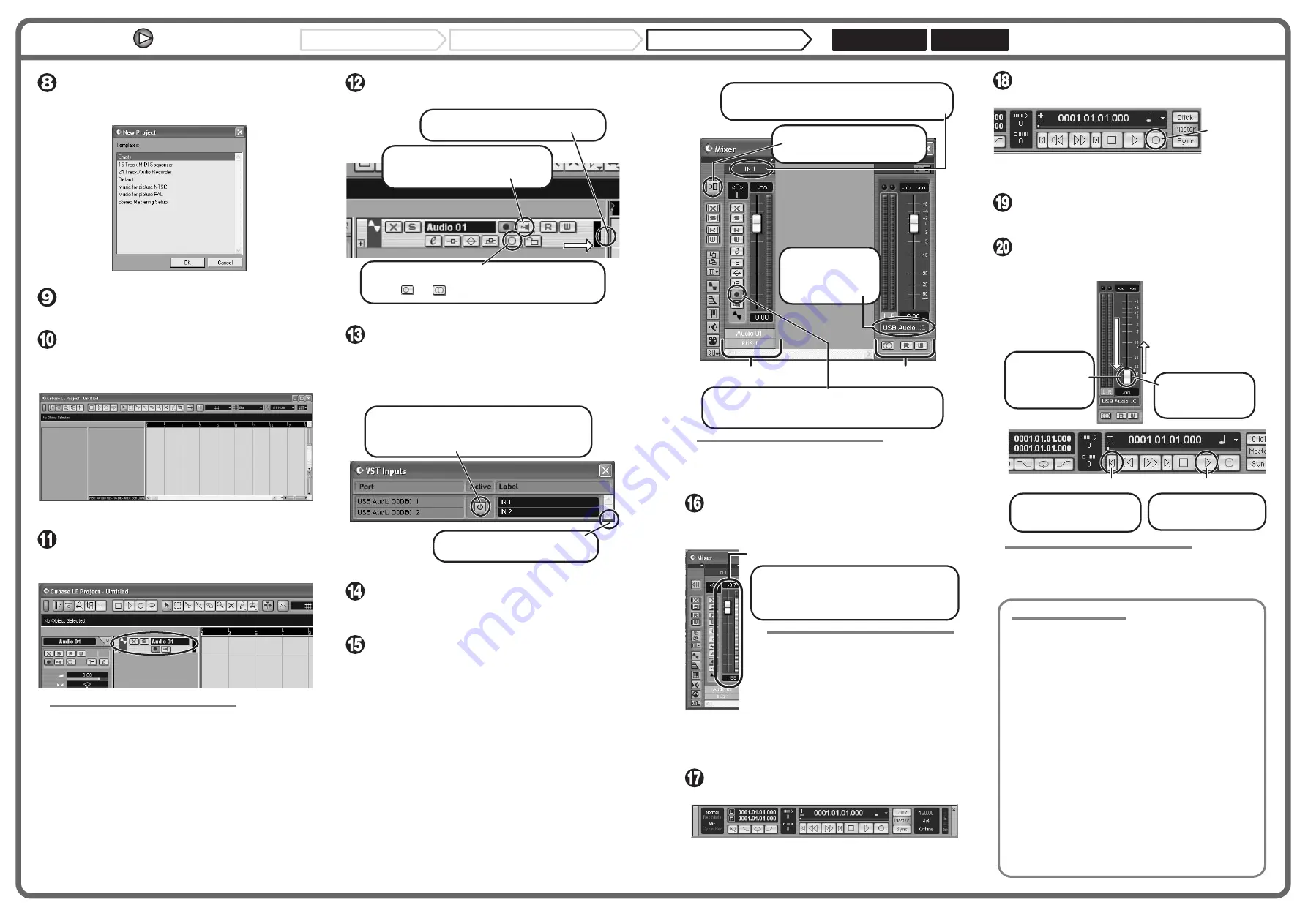
template. 


Make sure that the "Empty" template is selected, and 
click the OK button. 


A window for selecting the project file save location appears. 


After specifying the project file save location (such as 
the desktop), click the OK button (Choose button in 
MacOS 10.4). 


A new project is created, and the project window for controlling most
of the Cubase LE operations appears. 


To create a new audio track, access the "Project" 
menu and select "Add track". In the submenu that 
appears, select "Audio". 


A new audio track is added to the project window. 


HINT 


You can add several tracks at once by accessing the "Project" menu, 
selecting "Add track" and then selecting "Multiple..." in the submenu. 


Make the following settings for the new audio track. 

Access the "Devices" menu and select "VST Inputs". 


The VST inputs window appears. 
This window shows the available input ports and their active/inactive
status. 

You can perform the following steps here. 


Connect the guitar or other instrument to the [INPUT] 
jack of this unit and select the desired patch. 


The sound selected here will be recorded on the computer via the
[USB] port. 


Access the "Devices" menu and select "Mixer". 


The mixer window appears. 
This window shows the channels assigned to created tracks. 

You can perform the following steps here. 

Project window 

Drag the audio track boundary to the right 
to display all buttons. 

Verify that the Monitoring On button is 
Off (grayed out). If the button is On, 
click the button to turn it Off. 

Click the Stereo/Mono button to set the audio track to 
Stereo. When the button is not grayed out and has changed 
from [       ] to [       ], the track is active as a stereo track. 

1.

2.

3.

VST input window

Verify that the Active button for USB Audio CODEC 
1/2 (USB Audio CODEC L/R on MacOS X) is enabled 
(not grayed out). If the button is grayed out, click the 
button to enable it. 

2.

When there are multiple input ports, 
drag here to enlarge the window. 

1.


HINT 


When the Record Standby button is enabled, the level meter next to 
the fader shows the input level for the audio track. When the button is 
disabled, the output level for the audio track is shown. 


While playing your instrument, adjust the output level 
of this unit to achieve a suitable recording level for 
Cubase LE. 


Verify that the transport panel is shown. 


If the transport panel is not shown, access the "Transport" menu and
select "Transport Panel". 


To start recording, click the Record button in the 
transport panel. 


As you play your instrument, the waveform appears in real time in the
project window. 


To stop recording, click the Stop button in the 
transport panel. 


Recording stops. 


Check the recorded content. 


To play the recording, perform the following steps. 


HINT 


If no sound is heard when you click the Play button after recording, 
check the settings in the VST input window (step 13) and the master 
channel output port setting (step 15) once more. 


For optimum enjoyment 


While using Cubase LE, other applications may slow down drastically 
or the message "Cannot synchronize with USB audio interface" may 
appear. If this happens frequently, consider taking the following steps 
to optimize the operation conditions for Cubase LE. 


(1) Shut down other applications besides Cubase LE. 


In particular, check for resident software and utilities. 


(2) Reduce plug-ins (effects, instruments) used by Cubase LE.


 When there is a high number of plug-ins, the computer's 
processing power may not be able to keep up. Reducing 
the number of tracks for simultaneous playback can also be 
helpful. 


(3) Power the unit from an AC adapter


When a device designed to use USB power is powered via 
the USB port, the current supply may sometimes fluctuate, 
leading to problems. See if using an AC adapter improves 
operation.


If applications still run very slowly or the computer itself does not 
function properly, disconnect this unit from the computer and shut 
down Cubase LE. Then reconnect the USB cable and start Cubase LE 
again. 

Channel assigned to audio track 

Mixer window 

Master channel 

Verify that the Record Standby button is shown in red. (If 
the button is grayed out, click the button to enable it. This 
will set the audio track to the recording standby condition.) 

3.

Click here to select the port for the USB Audio CODEC 
1/2 (USB Audio CODEC L/R on MacOS X) assigned as 
audio input port to the channel (see step 13). 

2.

To adjust the playback level after 
recording, click this button to bring 
up the master channel of the mixer. 

1.

Click here to set the 
audio output port of 
the master channel 
to "USB Audio 
CODEC". 

4.

Level meter 

When the audio track is in recording standby mode, 
its recording level is shown by the level meter for the 
assigned channel. The level should be set in such a 
way that the meter registers to a fairly high value but 
remains below the maximum point. 

NOTE 

• The level meter shows the signal level after 

internal processing by Cubase LE. Therefore 
a slight time lag may occur between playing a 
guitar or other instrument and the meter 
registering the change in level. This is normal 
and not a defect. 

• The audio tracks of Cubase LE will be 

recorded with correct timing exactly matched 
to your instrument play. There will be no lag 
between already recorded tracks and newly 
added tracks. 

Transport panel 

Record button 

Go to beginning of project 

Play button 

Move the fader 
of the master 
channel (as 
displayed in step 
15) fully down. 

1.

Raise the fader of 
the master channel 
to obtain a suitable 
volume. 

4.

Use the controls on the 
transport panel to move to 
the beginning of the project. 

2.

Click the Play button in 
the transport panel to 
start playback.

3.


Continued from front 


Cubase LE Installation

Windows XP

MacOS X

Connections and Preparations

Recording with Cubase LE

Summary of Contents for g9.2tt

Page 1: ...Operation Manual ZOOM Corporation Reproduction of this manual in whole or in part by any means is prohibited ...

Page 2: ...G9 2tt included electromagnetic interference can cause malfunctioning and can corrupt or destroy data Care should be taken to minimize the risk of damage Cleaning Use a soft dry cloth to clean the G9 2tt If necessary slightly moisten the cloth Do not use abrasive cleanser wax or solvents such as paint thinner or cleaning alcohol since these may dull the finish or damage the surface Please keep thi...

Page 3: ...ion Effect module As shown in the illustration below the G9 2tt can be thought of as a combination of several single effects Each of these is referred to as an effect module The G9 2tt offers a compressor effect module COMP amp simulator distortion effect module PRE AMP external effect loop control module EXT LOOP and more Parameters such as effect intensity can be adjusted for each module individ...

Page 4: ... connector PHONES jack EXT LOOP GAIN 10 dBm 4 dBm switch EXT LOOP RETURN jack EXT LOOP SEND jack AUX IN jack LEVEL knob USB port Controls and Functions ZOOM G9 2tt 7 Control section Accelerator section Pre amp section TYPE knob PEDAL 1 SETTING key EXIT key BYPASS TUNER key AMP SELECT SYSTEM key STORE SWAP key PAGE key SOLID STATE control TUBE control Energizer section BOOST control TUBE control AM...

Page 5: ...he SEND RETURN jacks settings such as effect on off and send return level can be stored as part of a patch For details see page 41 Connection example 3 External effect connection External effect 1 Make sure that any connected guitar amplifier is turned off In addition fully turn down the volume control at the guitar amplifier 2 Plug the AC adapter into an AC outlet and plug the cable from the adap...

Page 6: ...se the BANK W Q foot switches to select the group bank and then use foot switches 1 5 1 To select a patch use foot switches 1 5 1 In play mode keep the BANK W foot switch depressed for more than one second Quick Guide 1 Play Mode Manual Mode Operation ZOOM G9 2tt 11 É Ch AB É BpmTp AmpDrive LVL100 U0 Pre amp operation HINT NOTE 2 Press the foot switch for the module to be switched on and off 3 To ...

Page 7: ...igned to the knobs see page 60 75 Quick Guide 2 Edit Mode Store Mode Operation ZOOM G9 2tt 13 Depth 100 é MOD Chorus STORE STORE åU0 1 U0 1 é NEWDrive NEWDrive PATCH PATCH U0 U0 Storing a patch store mode HINT NOTE In this condition you can store individual patches If the display is different use parameter knob 2 to bring up the STORE indication and parameter knob 3 to bring up the PATCH indicatio...

Page 8: ... bank use the BANK W Q foot switches to change the bank and then use foot switches 1 5 to select the patch When you repeatedly press the BANK Q foot switch the G9 2tt switches the group bank as follows HINT In play mode you can switch the group bank by turning the TYPE knob NOTE When using the BANK W Q foot switches to change banks press and release the switch quickly If you keep the BANK W foot s...

Page 9: ...in each band Parameter value Name of currently adjusted parameter SOLID STATE control TUBE control Selecting Patches for Playing Play Mode ZOOM G9 2tt 17 TUBE control This control adjusts the input signal gain of the tube circuit Turning the control clockwise increases gain and also increases distortion Settings higher than about three o clock will drastically increase the volume and distortion Th...

Page 10: ...rrently selected patch Shows the number of the parameter knob that controls the patch level CHANNEL A B keys The key for the channel A or B that is currently selected for the pre amp section is lit Function foot switch 1 2 assignment Effect module keys Keys for modules that are active in the currently selected patch are lit in red Shows the function assigned to the function foot switch 1 2 p 38 Fo...

Page 11: ... mode or edit mode press and hold the BANK Q foot switch To use the tuner the G9 2tt must be set to the bypass condition effects off or mute condition original sound and effect sound both off To switch to the bypass condition Hold the BANK Q foot switch for about 1 second until the indication BYPASS appears on the display Then release the foot switch The G9 2tt is now in the bypass condition HINT ...

Page 12: ... CHROMATC 442Hz 442Hz Using the Internal Tuner Bypass Mute Condition ZOOM G9 2tt 23 STR1 STR2 STR3 STR4 STR5 STR6 STR7 GUITAR BASS OPEN A OPEN G OPEN E OPEN D DADGAD G D A E B E B G D A E B E DB A E A E D A GB D A D E B AB E B E D B G D G D D A G D A D Tuner type String number of Using the chromatic tuner The display shows the tuning indication 2 Turn parameter knob 2 to select the tuner type The ...

Page 13: ... for modules that are OFF are not lit When you press Module name Parameter number Currently selected parameter and its setting value Effect type name Module other than PRE AMP EQ Depth 100 Depth 100 MOD Chorus MOD Chorus Changing the Sound of a Patch Edit Mode ZOOM G9 2tt 25 COMP key EQ key MOD EFX2 key REVERB key WAH EFX1 key EXT LOOP key PRE AMP key CABINET key DELAY key TOTAL FUNCTION key ZNR k...

Page 14: ...odule is automatically selected When an EQ parameter is adjusted the EQ module is automatically selected The PRE AMP ZNR and EQ modules allow separate parameter settings for the two channels A B Select the channel first and then adjust the parameter 5 Repeat steps 2 4 to edit other modules in the same way 6 When editing is finished press the EXIT key The G9 2tt returns to the previous mode Changin...

Page 15: ... NEWDrive PATCH PATCH STORE STORE åU0 1 U0 1 é NEWDrive NEWDrive PATCH PATCH Storing Patches and Banks Store Mode ZOOM G9 2tt 29 5 Use parameter knob 1 or the foot switches 1 5 to select the store swap target patch number 6 Press the STORE SWAP key once more The store swap process is carried out and the G9 2tt then returns to the play mode with the store swap target patch being selected By pressin...

Page 16: ...control targets in the vertical direction P2V1 to P2V4 and four control targets in the horizontal direction P2H1 to P2H4 A parameter can be assigned for each control target With a setting such as shown in the example at right the pedal adjusts the Gain parameter of the PRE AMP module when moved in the vertical direction and the Rate parameter of the MOD EFX2 module when moved in the horizontal dir...

Page 17: ...ZOOM G9 2tt 33 HINT The available range setting depends on the parameter selected in step 4 It is also possible to set min to a higher value than MAX In that case the parameter value will be minimum when the pedal is fully depressed and maximum when the pedal is fully raised 6 To use expression pedal 1 for switching the module on and off turn parameter knob 4 and select Enable Expression pedal 1 h...

Page 18: ...L2 V Target1 é MAX 100 MAX 100 PDL2 V Target1 PDL2 V Target1 é Switch Enable Switch Enable PDL2 V Target1 PDL2 V Target1 é Using the Expression Pedals ZOOM G9 2tt 35 8 To assign control targets for the horizontal direction turn the TYPE knob to select one of the four horizontal direction control targets P2H1 to P2H4 The display changes as follows The operation steps for setting the horizontal dire...

Page 19: ...follows PEDAL1 MAX PEDAL1 MAX PDL Calibration PDL Calibration Push strongly so that pedal touches here When foot is lifted pedal returns slightly PEDAL2 V min PEDAL2 V min PDL Calibration PDL Calibration Pedal fully raised PEDAL2 V MAX PEDAL2 V MAX PDL Calibration PDL Calibration Push strongly so that pedal touches here When foot is lifted pedal returns slightly Using the Expression Pedals ZOOM G9...

Page 20: ...lustration on next page BPM 120 BPM 120 TOTAL Tempo TOTAL Tempo PRE AMP CH A B PRE AMP CH A Bé TOTAL Function1 TOTAL Function1 BPM TAP BPM TAP é TOTAL Function2 TOTAL Function2 Function assigned to function foot switch 1 Function assigned to function foot switch 2 When parameter knob 2 is turned When parameter knob 3 is turned Using the Function Foot Switches ZOOM G9 2tt 39 Function foot switch pr...

Page 21: ...t note ƒ Dotted sixteenth note π Eighth note Ø 3 Half triplet note π Dotted eighth note Quarter note Dotted quarter note x2 Quarter note x 2 x20 Quarter note x 20 ZOOM G9 2tt 41 Using the Effect Loop The EXT LOOP SEND RETURN jacks on the rear panel of the G9 2tt allow connection of a compact effect rack mount effect or similar Settings for external effect on off and send return level can be stored...

Page 22: ...ch action This makes it possible to have patches at the G9 2tt switched automatically under control of a MIDI sequencer or link operation of the G9 2tt to patch switching at other MIDI enabled effects Send and receive pedal switch key operation information via MIDI When you operate specific keys and foot switches of the G9 2tt or operate the expression pedals 1 2 the MIDI OUT connector carries the...

Page 23: ...IT Y STORE N EXIT Store Store MIDI Usage Examples ZOOM G9 2tt 45 1 In play mode press the AMP SELECT SYSTEM key 2 To enable the G9 2tt to receive program change bank select messages turn the TYPE knob to bring up the MIDI PC Rx receive program change parameter and turn parameter knob 1 to select the ON setting 3 To enable the G9 2tt to send program change bank select messages turn the TYPE knob to...

Page 24: ...ched MIDI OUT connector MIDI IN connector 1 When a program change bank select message is received 2 Patch at the G9 2tt is switched MIDI OUT connector MIDI IN connector FRONT FRONT AMP Select 1 28 AMP Select 1 28 DIRECT DIRECT MIDI PCMODE 6 28 MIDI PCMODE 6 28 MIDI Usage Examples ZOOM G9 2tt 47 4 Turn the TYPE knob to bring up the PC MAP program change map parameter Using this display you can assi...

Page 25: ...28 Control change number to be assigned PEDAL1 7 PEDAL1 7 MIDI cc 12 28 MIDI cc 12 28 PEDAL1 7 PEDAL1 7 MIDI cc 12 28 MIDI cc 12 28 MIDI Usage Examples ZOOM G9 2tt 49 4 Assign control change numbers to other operations in the same way 5 When the setting is complete press the EXIT key to exit the AMP SELECT SYSTEM menu The indication Store appears on the display to allow you to store the changes 6 ...

Page 26: ...t NOTE When patch data are received all existing patch data in the G9 2tt will be overwritten Perform the following steps with care to avoid accidentally overwriting important data 1 Connect the MIDI OUT connector on the source G9 2tt to the MIDI IN connector on the target G9 2tt using a MIDI cable 1 When a control change message is received 2 The same operation as when the respective expression p...

Page 27: ...MOD Chorus MOD Chorus ARRM Mix ARRM Mix Minimum value Maximum value MAX 100 MAX 100 TOTAL ARRM MAX TOTAL ARRM MAX min 0 min 0 TOTAL ARRM min TOTAL ARRM min Other Functions ZOOM G9 2tt 53 HINT The available range setting depends on the parameter It is also possible to set min to a higher value than MAX In that case the control change direction will be reversed 5 To select the control waveform type ...

Page 28: ...orming playback with the DAW application the playback sound from the audio Other Functions ZOOM G9 2tt 55 tracks is mixed with the guitar sound processed by the effects of the G9 2tt and appears at the OUTPUT jack of the G9 2tt see Figure 2 on the previous page If required the guitar signal after effect processing can be muted during playback see Figure 3 on the previous page For details see next ...

Page 29: ...Q ZNR Noise Gate Dirty Gate PRE AMP ZNR EQ COMP WAH EFX1 EXT LOOP MOD EFX2 REVERB DELAY CABINET EQ ZNR Noise Gate Dirty Gate PRE AMP ZNR EQ FD Clean VX Clean JC Clean HW Clean Linking Effects The patches of the G9 2tt can be thought of as ten serially linked effect modules as shown in the illustration below You can use all effect modules together or selectively set certain modules to off to use ju...

Page 30: ...ve effect type is not selected 1 In play mode manual mode or edit mode press the WAH EFX1 key 2 Turn the TYPE knob and select an effect type other than Booster Tremolo or Octave 3 Turn parameter knob 1 to select Befr before pre amp section or Aftr after pre amp section FRONT FRONT AMP Select 1 28 AMP Select 1 28 Linking Effects ZOOM G9 2tt 59 EQ PRE AMP EXT LOOP ZNR Fig 1 Pre amp section PRE WAH E...

Page 31: ... functions the respective function must be assigned to the function foot switch 1 2 p 38 and the respective effect type must be enabled Effect module Effect Types and Parameters How to read the parameter table Effect Types and Parameters ZOOM G9 2tt 61 COMP module Attenuates high level signal components and boosts low level signal components to keep the overall signal level within a certain range ...

Page 32: ...tion position of the WAH EFX1 module Available settings are Befr before pre amp section or Aftr after pre amp section Adjusts the rise time Adjusts the rising volume change curve Adjusts the signal level after passing the module Effect Types and Parameters ZOOM G9 2tt 63 PedalVox Simulation of the vintage Vox pedal wah See PedalCry next effect for effect parameters PedalCry Simulation of the vinta...

Page 33: ...y guitarists of many music styles Clean sound of the combo amp VOX AC 30 operating in class A JC Clean HW Clean Clean sound of the Roland JC series with built in chorus which gives a wide clear tone Clean sound of the legendary all tube Hiwatt Custom 100 from Britain UK Blues US Blues Crunch sound of the 30 watt combo amp Marshall 1962 Bluesbreaker Crunch sound of a Fender Tweed Deluxe 53 TweedBas...

Page 34: ...Y module Effect Types and Parameters ZOOM G9 2tt 67 EQ module This is a 6 band equalizer In edit mode the module is adjusted using the BASS MIDDLE TREBLE and PRESENCE knobs of the pre amp section and the parameter knobs 3 and 4 BASS MIDDLE TREBLE PRESENCE Bass 12 160Hz Middle 12 800Hz Treble 12 3 2kHz Presence 12 6 4kHz Adjusts boost cut in the low frequency range Adjusts boost cut in the middle f...

Page 35: ...p Down Up Down Up Down Up Down 1 2 3 4 100 cent Original sound only DOUBLING Detune DRY 0 cent 1 octave 0 cent 2 octaves Original sound only 100 cent Detune DRY DOUBLING 1 octave 0 cent 2 octaves 0 cent Color Mode Up Down Up Down Up Down Up Down 5 6 7 8 1 octave DRY 1 octave DRY 700 cent DRY 500 cent DRY 0 Hz DRY 1 octave 0 Hz DRY 1 octave DRY 1 octave DRY 1 octave DRY 500 cent DRY 700 cent DRY 1 ...

Page 36: ...und also changes accordingly 6 5 4 3 m m Sixth down Fifth down Fourth down Third down Third down Third up Major scale Minor scale Setting Type of scale Interval 3 4 5 6 Third up Fourth up Fifth up Sixth up Major scale Setting Type of scale Interval Effect Types and Parameters ZOOM G9 2tt 71 Cry This effect varies the sound like a talking modulator PARM1 PARM2 PARM3 PARM4 Range 1 10 Resonance 0 10 ...

Page 37: ...ct Types and Parameters ZOOM G9 2tt 73 REVERB module This module comprises various kinds of reverb early reflections and multi tap delay Effect parameters are described below after effect types Hall This reverb effect simulates the acoustics of a concert hall Room This reverb effect simulates the acoustics of a room Spring This effect simulates a spring type reverb Arena This reverb effect simulat...

Page 38: ...action of function foot switch 2 NAME Specifies a name for the patch p 27 ARRM Makes settings for the ARRM function p 52 Use the PAGE key to switch between page 1 and 2 PAGE1 PARM1 PARM2 PARM3 ARRM control target min minimum value See page 52 MAX maximum value See page 52 Selects the ARRM control target When NOT Assign is selected the ARRM function is disabled Specifies the parameter value that is...

Page 39: ...of the other MIDI device and the MIDI OUT connector of the G9 2tt and the MIDI IN connector of the other MIDI device are connected properly Check the MIDI channel setting p 43 Check whether send receive of the respective type of MIDI message is enabled p 44 47 On off switching with expression pedal does not work properly Verify that parameter 4 module on off for expression pedal 1 P1 1 to P1 4 or ...

Page 40: ... 0 0 0 0 1 0 0 2 0 0 3 0 0 4 1 0 0 5 0 0 6 0 0 7 0 0 8 0 0 9 2 0 0 10 0 0 11 0 0 12 0 0 13 0 0 14 3 0 0 15 0 0 16 0 0 17 0 0 18 0 0 19 4 0 0 20 0 0 21 0 0 22 0 0 23 0 0 24 5 0 0 25 0 0 26 0 0 27 0 0 28 0 0 29 6 0 0 30 0 0 31 0 0 32 0 0 33 0 0 34 7 0 0 35 0 0 36 0 0 37 0 0 38 0 0 39 8 0 0 40 0 0 41 0 0 42 0 0 43 0 0 44 9 0 0 45 0 0 46 0 0 47 0 0 48 0 0 49 u 0 0 0 50 0 0 51 0 0 52 0 0 53 0 0 54 1 0 ...

Page 41: ...nstalled and used in accordance with the instructions may cause harmful interference to radio communications However there is no guarantee that interference will not occur in a particular installation If this equipment does cause harmful interference to radio or television reception which can be determined by turning the equipment off and on the user is encouraged to try to correct the interferenc...

Page 42: ...rameter PARM1 PARM2 PARM3 PARM4 Time 10 ñ 1000 FeedBack 0 ñ 100 HiDamp 0 ñ 10 Mix 0 ñ 100 Adjusts the delay time Adjusts the amount of feedback Higher setting values result in a higher number of delay sound repetitions Adjusts the amount of treble damping in the delay sound Lower setting values result in softer delay sound Adjusts the level of the effect sound mixed to the original sound X Flanger...

Page 43: ...uency spectrum that characterize vowels vertical direction of pedal Adjusts the formant peaks in the acoustic frequency spectrum that characterize vowels horizontal direction of pedal Table 3 The table below shows an example for Z pedal operation when vertical direction is assigned to Formant V and horizontal direction to Formant H REVERB module Z Delay This is a delay effect which allows adjustme...

Page 44: ...led on the Marshall Bluesbreaker A B DelayTAP FD Clean UK Blues Echo Mix ModernSpring Mix u6 1 v6 1 KingTone Ultimate clean tone recreating the saturation of a tube amp Select either American Fender sound channel A or British Vox sound channel B By making use of the Energizer tube circuitry the sound can be given additional sheen A B Hold Delay FD Clean VX Clean ModernSpring Mix AnalogDelay Mix u0...

Page 45: ...ie album The quality feel of the sound will have you swinging in a heartbeat The TweedBass setting in channel A has reduced gain and a less pronounced tone A B PRE AMP on TweedBass TweedBass ModernSpring Mix Echo Mix u7 4 v7 4 B Setzer Simulates the sound of guitar magician Brian May who created the dramatic allure of Queen Use the Z pedal to blend the alternating right left delay with the harmoni...

Page 46: ...t model was called Mark I Carlos Santana tried one and said Shit man that little thing really Boogies which gave the amplifier the brand name BOOGIE The second model Mark II had lead and rhythm channels and a 4 band equalizer to give wider variety to the guitar tone The special feature of this model was an accomplished simul power circuitry the operation could be switched between class A and class...

Page 47: ...behind the typical RAT sound In the Zoom G series this effect is simulated by the TONE parameter but operation is reversed treble is cut when turned counterclockwise PROCO RAT RAT MXR a company founded in the seventies by two high school students is famous for stomp boxes such as the Dynacomp and Phase 90 In the early days their products were actually built and painted in a garage and set out to d...

Page 48: ...appears Check whether the input port is active If the Active button is Off grayed out click the button to set it to On HINT When multiple input ports are available for selection you should scroll or enlarge the window and check the enable disable settings for all ports INPUT jack Computer Guitar or other instrument AC adapter Batteries or USB cable This unit OUTPUT jack Audio system or other hi fi...

Page 49: ... heard when you click the Play button after recording check the settings in the VST input window step 13 and the master channel output port setting step 15 once more For optimum enjoyment While using Cubase LE other applications may slow down drastically or the message Cannot synchronize with USB audio interface may appear If this happens frequently consider taking the following steps to optimize ...

Page 50: ...p After startup select ZOOM ASIO Driver as the ASIO driver in the right section of the Device Setup window When you change the ASIO driver selection a confirmation message appears Click the Switch button The device indication in the left section of the window now shows ZOOM ASIO Driver as the ASIO driver Click on this indication to select it and then click the Control Panel button in the right sec...

Page 51: ...ad change the recording level and gain settings at this unit NOTE While the monitoring button is enabled the direct signal input to this unit and the signal routed to the computer and then returned to this unit will be output simultaneously from this unit causing a flanger like effect in the sound To accurately monitor the sound also while adjusting the recording level temporarily set the output d...

Reviews: