


MIDI Usage Examples
ZOOM G7.1ut
42
■
Enable control change send/
receive
The procedure for enabling send/receive of
control change messages is described below.
1.
In play mode, press the [AMP
SELECT/SYSTEM] key.
2.
To enable the G7.1ut to receive
control change messages, turn the
[TYPE] knob to bring up the “MIDI
CTRL Rx” (receive control change)
parameter and turn parameter knob 1
to select the “ON” setting.
3.
To enable the G7.1ut to send control
change messages, turn the [TYPE]
knob to bring up the “MIDI CTRL Tx”
(send control change) parameter and
turn parameter knob 1 to select the
“ON” setting.
4.
When the setting is complete, press
the [EXIT] key to exit the AMP
SELECT/SYSTEM menu.
The indication “Store...?” appears on the display,
to allow you to store the changes.
5.
Press the [STORE/SWAP] key to save
the changes.
The setting is accepted, and the unit returns to
play mode.
In the above condition (while “Store...?” is
shown), only the [STORE/SWAP], [EXIT], and
[PAGE] keys are active. By pressing the [EXIT]
key, you can abort the changes and return to play
mode without saving.
■
Assigning control change
numbers
You can assign control change numbers to the
expression pedal and keys of the G7.1ut as
follows.
NOTE
Before carrying out the following steps, verify that
the send/receive MIDI channel setting of the
G7.1ut is as required (
→
p. 37), and that send/
receive of control change messages is enabled (
→
p. 41).
1.
In play mode, press the [AMP
SELECT/SYSTEM] key.
2.
Turn the [TYPE] knob to bring up the
display for assigning a control change
number.
Operations to which a control change number can
be assigned are listed in the table on the next
page.
For example, to assign a control change number
to the built-in expression pedal, the following
display is used.
¡FRONT
FRONT
AMP Select 1/26
AMP Select 1/26
¡CTRL Rx=ON
CTRL Rx=ON é
MIDI 10/26
MIDI 10/26
¡CTRL Tx=ON
CTRL Tx=ON é
MIDI 11/26
MIDI 11/26
Y[STORE] N[EXIT]
Y[STORE] N[EXIT]
Store...?
Store...?
¡FRONT
FRONT
AMP Select 1/26
AMP Select 1/26
Control change number to be assigned
¡PDL=11
PDL=11
MIDI cc# 13/26
MIDI cc# 13/26
MIDI Usage Examples
ZOOM G7.1ut
43
HINT
The control change number assignment always
applies both for sending and receiving.
3.
Turn parameter knob 1 to specify a
control change number.
4.
Assign control change numbers to
other operations in the same way.
5.
When the setting is complete, press
the [EXIT] key to exit the AMP
SELECT/SYSTEM menu.
The indication “Store...?” appears on the display,
to allow you to store the changes.
6.
Press the [STORE/SWAP] key to save
the changes.
The setting is accepted, and the unit returns to
play mode.
In the above condition (while “Store...?” is
shown), only the [STORE/SWAP], [EXIT], and
[PAGE] keys are active. By pressing the [EXIT]
key, you can abort the changes and return to play
mode without saving.
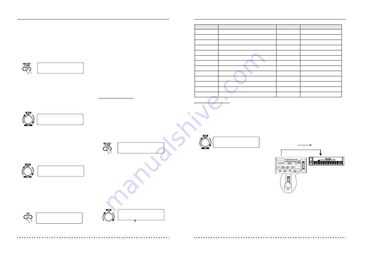
7.
To send and receive control change
messages, connect the G7.1ut and
the other MIDI device as follows.
■
Example for sending control change
messages
Control change values sent from the G7.1ut
change as follows.
●
When the built-in or external expression
pedal is operated
The value of the assigned control change
number is varied continuously over the range
of 0 – 127.
¡PDL=7
PDL=7 é
MIDI cc# 13/26
MIDI cc# 13/26
(2) Control change message is sent
(1) When the expression pedal or
switches and keys at the
G7.1ut are operated...
MIDI OUT
connector
MIDI IN
connector
Display
Control target
Default CC#
CC# setting range
CTRL IN
External expression pedal operation
7
OFF, 1 – 5, 7 – 31, 64 – 95
PDL
Built-in expression pedal operation
11
OFF, 1 – 5, 7 – 31, 64 – 95
COMP
COMP module on/off
64
OFF, 64 – 95
WAH/EFX1
WAH/EFX1 module on/off
65
OFF, 64 – 95
ZNR
ZNR module on/off
66
OFF, 64 – 95
PRE-AMP
PRE-AMP module on/off
67
OFF, 64 – 95
EQUALIZER
EQ module on/off
68
OFF, 64 – 95
MOD/EFX2
MOD/EFX2 module on/off
69
OFF, 64 – 95
DELAY
DELAY module on/off
70
OFF, 64 – 95
REVERB
REVERB module on/off
71
OFF, 64 – 95
MUTE
Mute mode on/off
72
OFF, 64 – 95
BYPASS
Bypass mode on/off
73
OFF, 64 – 95
CH A/B
Pre-amp section channel A/B switching
74
OFF, 64 – 95


