


Using the Function Foot Switch
ZOOM G7.1ut
36
4.
To synchronize a parameter to the
specified tempo, select the effect
type and effect parameter to
synchronize, and select the note
symbol as the setting value for the
parameter.
The setting value for effect parameters which
support tempo synchronization can be selected in
note units, using the patch specific tempo as a
reference.
For example, the Time parameter of the effect
type TAPE ECHO in the MOD/EFX2 module
supports patch specific tempo synchronization.
To use this capability, turn the respective
parameter knob from the maximum setting (2000)
further clockwise until a note symbol appears on
the display.
HINT
In the section “Effect Types and Parameters” (
→
p. 54 – 67), parameters which support tempo
synchronization are indicated by a note symbol.
5.
Select a parameter value by selecting
a note symbol.
The following settings are available.
NOTE
The actual available setting range depends on the
parameter.
When you have selected the eighth note setting,
the Time parameter will be set to a value that
corresponds to an eighth note in the patch specific
tempo. When the tempo is changed, the delay
time also changes accordingly.
NOTE
Depending on the combination of tempo setting
and selected note symbol, the maximum of the
parameter setting range (such as 2000 ms) may be
e x c e e d e d . I n s u c h a c a s e , t h e v a l u e i s
automatically halved (or set to 1/4 if the range is
still exceeded).
6.
When the tempo and parameter
setting is complete, press the [EXIT]
key.
The unit returns to play mode. Store the patch as
necessary.
The above procedure uses the tempo set in step 3
as reference for the note setting made in step 5.If
the “BPM TAP” function is assigned to the
[FUNCTION] (CH A/B) foot switch, you can
specify the tempo with your foot during a
performance and have the parameter change
accordingly.
√
Thirty-second note
ƒ
Sixteenth note
∑ 3
Quarter triplet note
ƒ ∫
Dotted sixteenth note
π
Eighth note
Ø 3
Half triplet note
π ∫
Dotted eighth note
∑
Quarter note
∑ ∫
Dotted quarter note
∑x 2
Quarter note x 2
:
:
∑x 20
Quarter note x 20
ZOOM G7.1ut
37
MIDI Usage Examples
This section describes the various MIDI functions of the G7.1ut.
What you can do with MIDI
The G7.1ut lets you use MIDI in various ways, as
described below.
●
Send and receive patch switching
information via MIDI
When you switch patches at the G7.1ut, the MIDI
OUT connector carries the corresponding MIDI
messages (program change, or bank
program change). Similarly, when a valid MIDI
message is received at the MIDI IN connector, the
G7.1ut will perform the corresponding patch
switch action.
This makes it possible to have patches at the
G7.1ut switched automatically under control of a
MIDI sequencer, or link operation of the G7.1ut
to patch switching at other MIDI enabled devices.
●
Send and receive pedal/switch/key
operation information via MIDI
When you operate specific keys and foot switches
of the G7.1ut, or operate the built-in or an
external expression pedal, the MIDI OUT
connector carries the corresponding MIDI
messages (control change). Similarly, when a
valid MIDI message is received at the MIDI IN
connector, the G7.1ut will vary the corresponding
parameter.
This makes it possible to use the G7.1ut as a real-
time controller for other MIDI enabled devices, or
alter effect parameters and module on/off status
under control of a MIDI sequencer, synthesizer,
or other MIDI enabled device.
●
Exchange patch data between two
G7.1ut units via MIDI
The patch data of the G7.1ut can be output as
MIDI messages (system exclusive), for copying
to another G7.1ut.
Selecting the MIDI channel
To enable correct sending and receiving of
program change, control change and other MIDI
messages, the MIDI channel (1 – 16) setting of
the G7.1ut and the other MIDI device must be
matched. To set the MIDI channel of the G7.1ut,
proceed as follows.
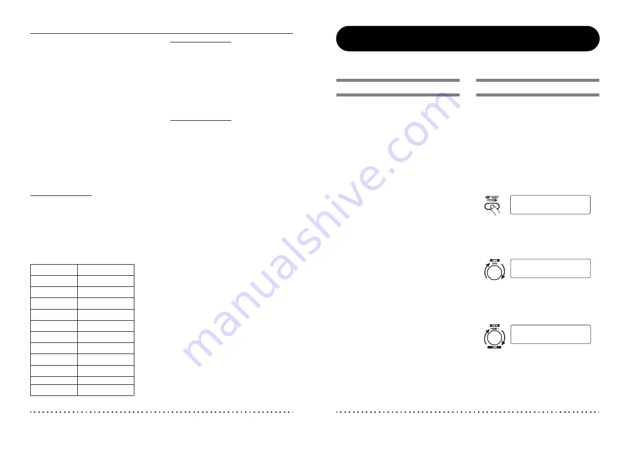
1.
In play mode, press the [AMP
SELECT/SYSTEM] key.
T h e A M P S E L E C T / S Y S T E M m e n u f o r
parameters that apply to all patches appears.
2.
Turn the [TYPE] knob to select the
“MIDI Rx Ch” (MIDI receive channel)
parameter.
3.
Turn parameter knob 1 to select the
MIDI channel (1 – 16) on which the
G7.1ut will receive MIDI messages.
4.
Turn the [TYPE] knob to select the
“MIDI Tx Ch” (MIDI transmit channel)
parameter.
¡FRONT
FRONT
AMP Select 1/26
AMP Select 1/26
¡Rx Ch=1
Rx Ch=1
MIDI 4/26
MIDI 4/26
¡Rx Ch=3
Rx Ch=3 é
MIDI 4/26
MIDI 4/26


