background image

ZONEMASTER MAXIPOINT V2 DAMPER CONTROL SYSTEM 

- Installation Manual


14


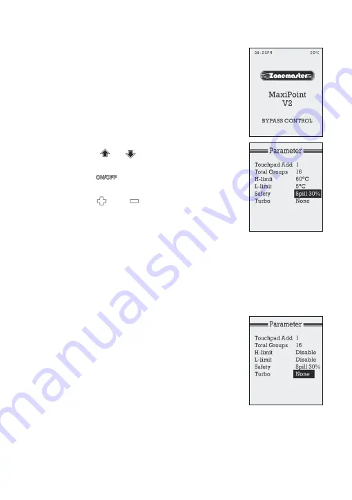
The factory default is set in spill mode and the  


set-point is 30%. When the set point is reached  


for spill, the screen shows ‘SPILL CONTROL’  


and some of the lower order zones remain open  


and will not respond to ON/OFF operation.  


Similarly if bypass set point is reached the  


screen displays ‘BYPASS CONTROL’ as shown  


in the right figure.


a) 

At the setting mode in ‘Parameter’ screen,  


press         or        button to select  


‘Safety Spill’. 


b) 

Press           button to select Spill or  


Bypass mode. 


c) 

Press         or          button to change  


the spill/bypass set-point to required  


value. The adjustable range is from 0%  


to 50% with 10% increments.


IMPORTANT: DO NOT set spill/bypass set-point to 0% unless there is  


a permanent open zone used as spill zone. Otherwise, there will be   


no spill zone when all zones are closed and damage may be caused  


by high pressure build up inside ducts if air conditioner is running. 


5)  Turbo Group


The Turbo function will give the selected group  


a full-opening while all the other groups  


(dampers) opening positions are reduced by  


50% of their balanced value. This will bring a  


large volume of extra air into the designated  


area and cool or heat the area quicker. Typically  


this may be a family-room, dining room or home  


theatre (or in commercial application a meeting,  


lunch or board room). (See Grouping Zones  


section for how to group).

Summary of Contents for MAXIPOINT V2

Page 1: ...MAXIPOINT V2 DAMPER CONTROL SYSTEM Installation Manual www zonemaster com au www polyaire com au 2009 Polyaire Pty Ltd ...

Page 2: ......

Page 3: ...bo Group 14 7 3 Grouping Zones 15 7 4 Balancing Zones 16 7 5 Naming Groups 17 7 6 Enabling Disabling Service Reminder 18 7 7 Enabling Disabling Temperature Display 19 7 8 Programming On Off Mode 20 1 Set Clock and Day 20 2 Adjust Program Time 21 3 Select Program for a Group 22 7 9 Testing Damper On Off 22 7 10 Wiring Diagram for MaxiPoint V2 23 TABLE OF CONTENTS Liability Please read the instructi...

Page 4: ...with up to 4 touchpads available in a system Manual and time programmable group on off control LCD on the touchpads for group status and parameter display Personalised group labelling 5 1 1 programmable on off time programs Remote zone balancing each zone s opening position can be programmed for balancing purpose via touchpad from 0 100 One selectable turbo group Auto spill bypass dedicated bypass...

Page 5: ...3 3 Motorized Damper Bright Green Motorized damper drives the blade of the damper to turn on off the air supply 3 4 Cables Cables with left latch or central latch plugs connect the main control module its extension module touchpads and motorized damper together 3 5 Supply Air Sensor Supply air sensor measures the temperature of the supply air for safety purposes 3 6 Power Supply 24VAC transformers...

Page 6: ...module In addition there is a dedicated bypass port where a damper is used to return the supply air directly to the return air duct See Spill Bypass Mode on Page 12 Extension Module An extension module can be plugged into the main control module to expand the number of zones to 16 as shown in Figure 2 A separate 24 VAC power supply is required for the power supply to the 8 extra zones The cabling ...

Page 7: ...shown in Figure 3 Touchpad is connected to the T port on main module using a cable with left latched plugs Up to 4 touchpads can be joined in a system The 4 touchpads are connected to each other with a double left latched adaptor Figure 2 MaxiPoint V2 with Extension Module and 8 Zone Ports Figure 3 MaxiPoint V2 with Main Control Module and Extension Module 4 Touchpads and 16 zone ports Dampers not...

Page 8: ...ents Each group initially has one zone but can have up to a maximum of 4 zones Example There could be 1 or more zones going into a common area such as Kitchen Dining or Family Dining room Work out the total group number Maximum total group number in a system is 16 5 4 Decide which group will have the Turbo function Record the above mentioned information to table 1 and 2 on page 8 in the Operation ...

Page 9: ...used connect main module to extension module at the E ports on both modules with a 1 metre left latched cable provided 6 4 Use pre tested cable to connect Z1 port on the main control module to the motorised damper of the 1st zone 6 5 Repeat step 6 4 to connect other zone dampers including bypass damper B port if installed to their relevant zone ports on the main control module and extension module...

Page 10: ...ormers main module and extension module share the same power switch switch the power on IMPORTANT NOTE If NOT switch on the power to extension module first Then turn on the power to main module Otherwise the extension module will NOT be initialised properly Circular Red LED on the main module and extension module should be on and the system will start initialising finish in about 30 seconds after ...

Page 11: ...ver to push the two notches at the bottom of the casing inside and turn the screwdriver blade just enough to open the cover as shown in the right figure 2 The bottom end opens up and the top end still remains attached 3 The top part is now removed by folding back the front section of the body thus releasing the clip from the notch of the back cover 4 Position the back cover on the wall about 1 5m ...

Page 12: ...a default address of None During commissioning each touchpad should be assigned a unique address for them to communicate with the main control module properly Follow the steps below to set Touchpad Address a At the setting mode select Parameter by pressing or button Then press button to enter Parameter screen b Use or button to select Touchpad Add highlighted c Use or button to select a touchpad a...

Page 13: ... Groups line c Press the or button to change the number to the total number of groups in the system The selectable number is 1 to 16 3 Supply Air Safety High Low Limits For safety reasons the system can monitor the supply air temperature If the temperature moves outside the set limits all dampers in the system are forced open The factory default setting is that the safety control is disabled Setti...

Page 14: ...limit and L limit protection is disabled there is about one minute delay after disabling the protection Check the air conditioning unit if SAFETY CONTROL displays at bottom of LCD screen 4 Spill Bypass Mode Bypass and spill modes are safety features of the MaxiPoint V2 system to prevent pressure from building up and causing duct damage This usually occurs if someone has turned off all the dampers ...

Page 15: ...t This may cause discomfort if bedrooms are used as spill zones When the spill set point is reached the main control module instructs zone 1 to open as spill If the first spill zone cannot satisfy the spill air control zone 2 will be forced to open to spill excess air This process will continue until the spill air set point is satisfied in the system Example In an 8 zone system if set point is set...

Page 16: ... to required value The adjustable range is from 0 to 50 with 10 increments IMPORTANT DO NOT set spill bypass set point to 0 unless there is a permanent open zone used as spill zone Otherwise there will be no spill zone when all zones are closed and damage may be caused by high pressure build up inside ducts if air conditioner is running 5 Turbo Group The Turbo function will give the selected group...

Page 17: ... zones are treated as one group with its own name and turned on or off together Individual balanced damper position is not affected by grouping which means zone balancing can be conducted before or after grouping Grouping can be carried out as follows a At setting mode press or button to select Grouping and press button to bring up Grouping screen b Press or button to highlight the group to which ...

Page 18: ...is highlighted to initiate balancing Then the numbers in the highlighted section starts blinking and the zone damper initiates to closed position d Press or button to increase or decrease the percentage of opening positions for the zone e Once the percentage has been set for the respective zone wait for about 15 seconds till words PLEASE WAIT at the bottom disappears Then press button again to con...

Page 19: ...Press or button to select the group to be named c Press or button to select one of the preset group names for the group d If user wants to make some changes to the preset name selected press button to initialize the change and then press and button to select the character to be changed e Then use or button to change the character as prefered There are 26 letters 10 numbers and a space to choose fr...

Page 20: ... if it has been enabled for 6 months 182 days or 2 years 728 days respectively since the air conditioning system being commissioned or serviced as shown in the right figure It is disabled by default but can be enabled as follows a In Setting menu select Service by highlighting it and follow by pressing to bring up next screen b In Service menu Name line is highlighted and installers name can be in...

Page 21: ...d go to CLOCK menu see the Set Clock and Day menu on page 20 highlight the Days line and press button once The alert will disappear after exiting CLOCK menu 7 7 Enabling Disabling Temperature Display The Temp Show feature allows to either enable disable the temperature displayed on the upper right hand of the LCD screen It is enabled as default but can be disabled as follows a In Setting menu sele...

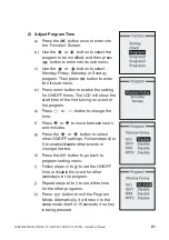
Page 22: ...f time 2 Monday to Friday 6 30AM 8 00AM 5 30PM 10 00PM Saturday 7 30AM 12 30PM 6 00PM 11 30PM Sunday 7 30AM 12 30PM 6 00PM 11 30PM NOTE The Turbo function cannot be programmed It is activated manually from the touchpad as needed 1 Set Clock and Day a Press the button once to enter into the Function Screen b Use the or button to select the Clock and then press button to enter the sub menu of the cl...

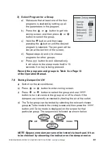
Page 23: ...CD will show the start time of the first turning on event of the program e Press or button to change the time f Press or to move between hours and minutes g Press the or button to select other ON OFF settings Follow steps d to f to enable disable other events or change the time h Press the button to go back to program setting menu i Follow steps c to g to set the ON OFF time or disable the event f...

Page 24: ...if no key is being pressed Record the programs and groups to Table 5 on Page 10 of the Operation Manual 7 9 Testing Damper On Off a Switch on the air conditioner b Press or button to enter zoning screen c Press or button to select the group and use button to turn all zones in the group on or off to check if the dampers are correctly connected by feeling the air at the outlet d The Turbo group can ...

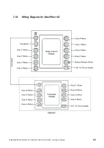
Page 25: ...ZONEMASTER MAXIPOINT V2 DAMPER CONTROL SYSTEM Installation Manual 23 7 10 Wiring Diagram for MaxiPoint V2 ...

Page 26: ......

Page 27: ......

Page 28: ...POLYAIRE PTY LTD 11 13 WHITE ROAD GEPPS CROSS SOUTH AUSTRALIA 5094 TEL 08 8349 8466 FAX 08 8349 8446 www zonemaster com au www polyaire com au ...

Reviews: