ECI2610 Network Motion Control Card Hardware Manual Version1.1
18
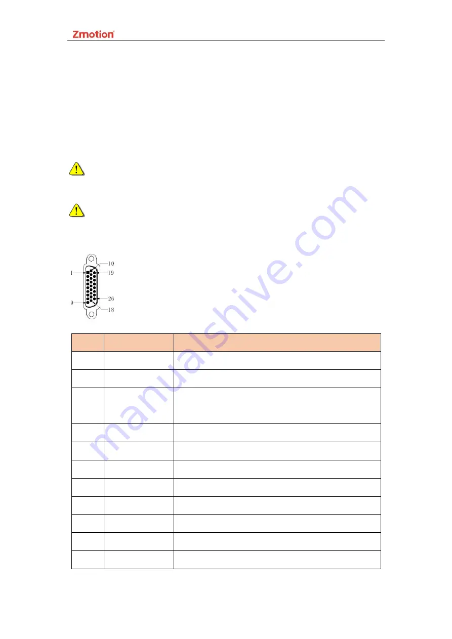
2.2.12 Axis Interface Signal
◆
Each terminal provides 0V and + 5V output, which also can provide 5V power for
the encoder.
◆
Do set its parameter ATYPE before use axis.
Alarm input, on-position signal and axis enable output can be used as general
input and output simultaneously.
Each axis has independent encoder except axis 4. Axis 4 is relative to encoder
axis 10, which is allocated as handwheel axis number by default.
PIN
Signal
Description
1
EGND
External power ground
2
IN24-29/ALM
General input, recommended to do drive alarm
3
OUT16-
21/ENABLE
General output, recommended to do drive enable
4
EA+
Encoder input
5
EB+
Encoder input
6
EZ+
Encoder input
7
+5V
Power input
8
Reserved
Reserved
9
DIR+
Servo/stepper directional output
10
GND
Digital ground
11
PUL-
Servo/stepper pulse output


