background image

InBio160/260/460 Pro Access Control Panel  


User Manual 


P a g e

 | 29 


Copyright©2020 ZKTECO CO., LTD.    All rights reserved.


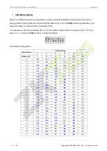
Place Address 

Switch Setting 

28 

OFF 

OFF 

ON 

ON 

ON 

OFF 

29 

ON


OFF 

ON 

ON 

ON 

OFF 

30 

OFF 

ON 

ON 

ON 

ON 

OFF 

31 

ON 

ON 

ON 

ON 

ON 

OFF 

32 

OFF 

OFF 

OFF 

OFF 

OFF 

ON 

33 

ON


OFF 

OFF 

OFF 

OFF 

ON 

34 

OFF 

ON 

OFF 

OFF 

OFF 

ON 

35 

ON 

ON 

OFF 

OFF 

OFF 

ON 

36 

OFF 

OFF 

ON 

OFF 

OFF 

ON 

37 

ON


OFF 

ON 

OFF 

OFF 

ON 

38 

OFF 

ON 

ON 

OFF 

OFF 

ON 

39 

ON 

ON 

ON 

OFF 

OFF 

ON 

40 

OFF 

OFF 

OFF 

ON 

OFF 

ON 

41 

ON 

OFF 

OFF 

ON 

OFF 

ON 

42 

OFF 

ON 

OFF 

ON 

OFF 

ON 

43 

ON


ON 

OFF 

ON 

OFF 

ON 

44 

OFF 

OFF 

ON 

ON 

OFF 

ON 

45 

ON 

OFF 

ON 

ON 

OFF 

ON 

46 

OFF 

ON


ON 

ON 

OFF 

ON 

47 

ON 

ON 

ON 

ON 

OFF 

ON 

48 

OFF 

OFF 

OFF 

OFF 

ON 

ON 

49 

ON 

OFF 

OFF 

OFF 

ON 

ON 

50 

OFF 

ON 

OFF 

OFF 

ON 

ON 

51 

ON 

ON 

OFF 

OFF 

ON 

ON 

52 

OFF 

OFF 

ON 

OFF 

ON 

ON 

53 

ON 

OFF 

ON 

OFF 

ON 

ON 

54 

OFF 

ON 

ON 

OFF 

ON 

ON 

55 

ON


ON 

ON 

OFF 

ON 

ON 

56 

OFF 

OFF 

OFF 

ON 

ON 

ON 

57 

ON 

OFF 

OFF 

ON 

ON 

ON 

58 

OFF 

ON


OFF 

ON 

ON 

ON 

59 

ON 

ON


OFF 

ON 

ON 

ON 

60 

OFF 

OFF 

ON 

ON 

ON 

ON 

61 

ON 

OFF 

ON 

ON 

ON 

ON 

62 

OFF 

ON 

ON 

ON 

ON 

ON 

63 

ON 

ON 

ON 

ON 

ON 

ON 


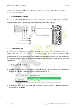
Restoring factory setting 

The silk-screened 

7

 (place 7) of the DIP switch is the switch for restoration of system settings. The place is 

set to 

OFF

 by default. When place 7 is moved upwards and downwards for three times within 10 seconds 

Summary of Contents for inBIO260

Page 1: ...e instructions carefully before operation Follow these instructions to ensure that the product is functioning properly The images shown in this manual are for illustrative purposes only For further details please visit our Company s website www zkteco com User Manual InBio160 260 460 Pro Access Control Panel Date November 2020 Doc Version 1 0 English ...

Page 2: ...y familiar with the design and that the said personnel have received thorough training in operating and maintaining the machine unit equipment It is further essential for the safe operation of the machine unit equipment that personnel has read understood and followed the safety instructions contained in the manual In case of any conflict between terms and conditions of this manual and the contract...

Page 3: ...s of the machine unit equipment and such amendments shall not give any right to claim any compensation or damages under any circumstances ZKTeco shall in no way be responsible i in case the machine unit equipment malfunctions due to any non compliance of the instructions contained in this manual ii in case of operation of the machine unit equipment beyond the rate limits iii in case of operation o...

Page 4: ...dent research and development of biometric verification procedures and the productization of biometric verification SDK which was initially widely applied in PC security and identity authentication fields With the continuous enhancement of the development and plenty of market applications the team has gradually constructed an identity authentication ecosystem and smart security ecosystem which are...

Page 5: ...nvention Description Button or key names for devices For example press OK Window names menu items data table and field names are inside square brackets For example pop up the New User window Multi level menus are separated by forwarding slashes For example File Create Folder Symbols Convention Description This implies about the notice or pays attention to in the manual The general information whic...

Page 6: ...INSTALLATION OF ACCESS CONTROL PANEL WIRES 12 3 2 CONTROL PANEL SYSTEM INSTALLATION 13 3 3 CONTROL PANEL CONNECTION TERMINALS 14 3 4 CONNECTION WITH DOOR SENSORS EXIT SWITCHES AUXILIARY INPUT DEVICES AND RS485 EXTENSION 3 5 COMMUNICATION 17 CONNECTION WITH READERS 19 3 6 RELAY OUTPUT CONNECTION 21 3 7 ACCESS CONTROL OPERATOR PANEL SYSTEM POWER SUPPLY STRUCTURE 23 3 8 4 EQUIPMENT COMMUNICATION 25 A...

Page 7: ...rapped with insulating tapes to prevent any damage to the equipment by accidental contact of the exposed wires 6 Repair Do not attempt to have an unauthorized repair of the equipment Disassembly or detachment is risky and likely to cause shock All repairs should be done by a qualified technician 7 If any of the following cases arise disconnect the power supply from the equipment first and intimate...

Page 8: ...e sure to unplug the connection terminals before starting any relevant welding job 3 Do not detach or replace any control panel chip without permission and an unpermitted operation may cause damage to the control panel 4 It is recommended not to connect any other auxiliary devices without permission All non routine operations must be communicated to our engineers in advance 5 A control panel shoul...

Page 9: ...e force during onsite connection for application of the access control system 12 It is recommended that an electronic lock and a control panel should use separate power supplies 13 It is recommended to use the power supply delivered with the system as the control panel power supply 14 In a place with substantial magnetic interference galvanized steel pipes or shielded cables are recommended and pr...

Page 10: ... reliable communications Control Panel with a watchdog hardware built in to prevent a crash Over current over voltage and inverse voltage protection for the input of the power supply to the control panel Over current protection for the power supply to card readers Instant over voltage protection for all input output ports Instant over voltage protection for communication ports Product Technical Pa...

Page 11: ...y Control Panel Indicators 2 3 When the InBio160 260 460 Pro is powered on normally the POWER indicator red is lit constantly the RUN indicator green shall flash slowly indicating the system is normal and other indicators are all off LINK indicator green indicates proper TCP IP connection if it is lit constantly ACT indicator yellow indicates transmission of TCP IP data if it flashes EXT RS485 TX ...

Page 12: ...ss Control Panel User Manual P a g e 11 Copyright 2020 ZKTECO CO LTD All rights reserved 3 Installation and Connection Installation Procedure 3 1 Appearance and Internal of the panel box Installation steps for the control panel ...

Page 13: ...cting the wires otherwise it may cause severe damage to the equipment The access control wires must be separated according to heavy and light current the control panel wires electronic lock wires and exit button wires must run through their casing pipes respectively Control Panel Door sensor Electronic lock Exit button Indoor wiegand card reader Outdoor wiegand card reader Ceiling TCP IP Network c...

Page 14: ...nBio160 260 460 Pro Access Control Panel User Manual P a g e 13 Copyright 2020 ZKTECO CO LTD All rights reserved Control Panel System Installation 3 3 Figure 3 2 Schematic Diagram of System Installation ...

Page 15: ...S485 network On a 485 bus each management workstation can be connected with up to 63 InBio Pro control operator panels preferably fewer than 32 The communication wires should be kept away from high voltage wires as far as possible and should be neither routed in parallel with nor bundled with power wires A management workstation is a PC connected with the network By running the access control mana...

Page 16: ...InBio160 260 460 Pro Access Control Panel User Manual P a g e 15 Copyright 2020 ZKTECO CO LTD All rights reserved InBio260 Pro Terminal connection diagram ...

Page 17: ...InBio160 260 460 Pro Access Control Panel User Manual P a g e 16 Copyright 2020 ZKTECO CO LTD All rights reserved InBio460 Pro Terminal connection diagram ...

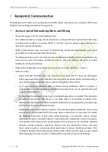
Page 18: ... records of access control for client Ports of InBio160 260 460 Pro Control Panel Connection with Door Sensors Exit Switches Auxiliary Input 3 5 Devices and RS485 Extension Communication 1 Door sensor A Door Sensor is used to sense the open close status of a door With a door sensor switch an access control panel can detect the unauthorized opening of a door and will trigger the output of alarm No ...

Page 19: ...4m above the ground Ensure it is located in the right position without slant and its connection is correct and secure Cut off the exposed end of any unused wire and wrap it with insulating tape Make sure to avoid electromagnetic interference such as light switches and computers It is recommended to use two core wires with a gauge over 0 3mm2 as the connection wire between an exit switch and the Co...

Page 20: ...re 3 4 Connection between inBio460 Pro and RS485 Readers A single EXT RS485 interface can supply for maximum 750 mA 12V current So the entire current consumption should be less than this max value when the readers share power with the panel For calculation please use max current of the reader and starting current is usually more than twice of the normal work current please consider this situation ...

Page 21: ...greater consumption we suggest to use the separately power supplies to make sure the steady operation Connection with Wiegand Readers The InBio160 Pro can connect two Wiegand readers in the one door two way mode The InBio260 Pro provides four readers which can be connected in the two door two way mode The InBio460 Pro provides four readers which can be connected in the two door two way or four doo...

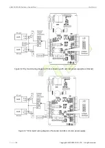
Page 22: ...ction 2 An access control panel provides multiple electronic lock outputs The COM and NO terminals apply to the locks that are unlocked when power is connected and locked when power is disconnected The COM and NC terminals use the locks that are locked when power is connected and unlocked when power is disconnected 3 To protect the access control system against the self induced electromotive force...

Page 23: ...l User Manual P a g e 22 Copyright 2020 ZKTECO CO LTD All rights reserved Figure 3 6 Dry mode wiring diagram of lock connecting with external power supply recommend Figure 3 7 Wet mode wiring diagram of lock and controller common power supply ...

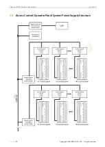
Page 24: ...InBio160 260 460 Pro Access Control Panel User Manual P a g e 23 Copyright 2020 ZKTECO CO LTD All rights reserved Access Control Operator Panel System Power Supply Structure 3 8 ...

Page 25: ...should be powered separately When high reliability is required control panels and electronic locks should be powered respectively To prevent power failure of a control operator panel from making the whole system unable to work normally the access control management system is usually required to have one UPS at least and access control locks are powered externally to guarantee the access control ma...

Page 26: ...If parallel wiring is unavoidable for environmental reasons the distance must be above 50cm Try to avoid using any conductor with a connector during distribution When a connector is indispensable it must be crimped or welded No mechanical force can be applied to the joint or branch of conductors In a building the distribution lines must be installed horizontally or vertically They should be protec...

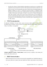
Page 27: ...t exceed 2 ohms Also the shielding layer must be connected reliably and grounded at one end to guarantee a uniform current direction The ground wire of the shielding layer must be connected through a large diameter wire not less than 2 5mm2 TCP IP Communication 4 2 The Ethernet 10 100Base T Crossover Cable a type of crossover network cable is mainly used for cascading hubs and switches or used to ...

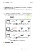
Page 28: ... the bus is longer than 300 meters one 120ohm resistance is usually inserted between the first and last access control operator panels on the RS485 bus 4 For this access control operator panel putting place 8 of the DIP switch to the ON position is equivalent to parallel connection of one 120ohm resistance between the 485 and 485 lines As shown in the figure below put place 8 of the DIP switches o...

Page 29: ...ddress setting table Place Address Switch Setting 1 2 3 4 5 6 Address No 1 2 4 8 16 32 01 ON OFF OFF OFF OFF OFF 02 OFF ON OFF OFF OFF OFF 03 ON ON OFF OFF OFF OFF 04 OFF OFF ON OFF OFF OFF 05 ON OFF ON OFF OFF OFF 06 OFF ON ON OFF OFF OFF 07 ON ON ON OFF OFF OFF 08 OFF OFF OFF ON OFF OFF 09 ON OFF OFF ON OFF OFF 10 OFF ON OFF ON OFF OFF 11 ON ON OFF ON OFF OFF 12 OFF OFF ON ON OFF OFF 13 ON OFF O...

Page 30: ... 43 ON ON OFF ON OFF ON 44 OFF OFF ON ON OFF ON 45 ON OFF ON ON OFF ON 46 OFF ON ON ON OFF ON 47 ON ON ON ON OFF ON 48 OFF OFF OFF OFF ON ON 49 ON OFF OFF OFF ON ON 50 OFF ON OFF OFF ON ON 51 ON ON OFF OFF ON ON 52 OFF OFF ON OFF ON ON 53 ON OFF ON OFF ON ON 54 OFF ON ON OFF ON ON 55 ON ON ON OFF ON ON 56 OFF OFF OFF ON ON ON 57 ON OFF OFF ON ON ON 58 OFF ON OFF ON ON ON 59 ON ON OFF ON ON ON 60 O...

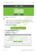
Page 31: ...y manage controllers the built in Web Server function is added to some models With this function a user can connect to the controller through a PC and enter the IP address of the controller to access the web Users can also use the Web Server function to perform other operations such as network configuration Push communication configuration time synchronization and user account management Log on to...

Page 32: ...ler must be in the same network segment 2 IP address of the controller could be found by searching devices with the BioSecurity software Access Access Device Device Search Device Basic Operation Bar of the Web Server 1 Change of the Administrator s Password a Click The following page is displayed b Enter the old and new passwords and click Confirm to change the administrator s login password 2 Lan...

Page 33: ...ge in which the server interface is displayed and click Confirm 3 Use Conditions of the Server Click and you can view the version of the current server as well as thebrowser and resolution recommended for the server 4 Online Help of the Server If you met some problems when using the server click to view or download the user help document ...

Page 34: ...right 2020 ZKTECO CO LTD All rights reserved 5 Exit Click and then click Confirm to return to the server login page Network Settings 1 TCP IP Settings Function introduction Set the TCP IP communication parameters which are used in the communications between device and PC ...

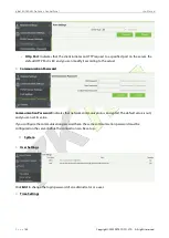
Page 35: ...fault Gateway the default gateway is 0 0 0 0 and you can modify it according to the actual Primary DNS the default value is null and you can set its value c Click Confirm to write parameters into the device please restart the device by manual Communication Settings 1 PUSH Server Settings PUSH Server Indicates that the controller proactively pushes information to the server IP Mode the default serv...

Page 36: ... can modify it according to the actual 3 Communication Password Communication Password Indicates that network communication is encrypted The default value is null and you can set its value If you configure the communication password here the same communication password must be configured on the server before the connection can be set up System 1 User Settings Click Edit to change the login passwor...

Page 37: ...pyright 2020 ZKTECO CO LTD All rights reserved You can manually configure the controller time or synchronize the controller time with the PC time and click Confirm to complete the setting 3 System Settings Click Reboot The device will be restarted 4 Device Information ...

Page 38: ...r privacy issues concerning your use of our product please directly contact your dealer Our other law enforcement fingerprint devices or development tools can capture the original images of citizen s fingerprints As to whether or not this constitutes an infringement of your rights please contact your Government or the final supplier of the device As the manufacturer of the device we will assume no...

Page 39: ... quantities Component Name Hazardous Toxic Substance Element Lead Pb Mercury Hg Cadmiu m Cd Hexavalent chromium Cr6 Polybrominate d Biphenyls PBB Polybrominated Diphenyl Ethers PBDE Chip Resistor Chip Capacitor Chip Inductor Diode ESD component Buzzer Adapter Screws indicates that the total amount of toxic content in all the homogeneous materials is below the limit as specified in SJ T 11363 2006 ...

Page 40: ...2020 ZKTECO CO LTD All rights reserved ZKTeco Industrial Park No 26 188 Industrial Road Tangxia Town Dongguan China Phone 86 769 82109991 Fax 86 755 89602394 www zkteco com Copyright 2020 ZKTECO CO LTD All Rights Reserved ...

Reviews: