


8
Installation instructions
802742UK V4.00 Sept 2018 - Zip HydroTap Industrial
Technical support
Tel: 0345 6 005 005 Email: [email protected] www.zipwater.co.uk
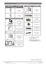
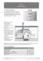
Major components and accessories
For Accessories contact Zip:
Tel 0345 6 005 005
Website: www.zipwater.co.uk
Email: [email protected]
*Dependant on model purchased
801599 - HydroTap User Guide - Nov 2013 UK - V1.05
Page 1 of 20
ZIP HydroTap
User Guide
®
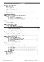
•
Tap Operation...................(Pages 2-5)
•
LCD Screen & Menu .......(Pages 6-18)
•
Maintenance.................... (Pages 18-20)
•
Date of Installation.........
Affix Model Number Label
Here
801599
BC160/125G4
BC240/175G4
BCH160/125G4
BCH240/175G4
AV160/125G4
AN160/125G4
AV240/175G4
AN240/175G4
801600 - Zip Quick Start Guide - October 2013 - V1.06
Parts Supplied
Description
Parts Supplied
Description
1 off
Hydrotap Tap
and hoses
Duct kit
1x Air Duct
1 x Mounting
plate
1 off
Undersink Unit
with air and water-
filter
Vent kit
1 x Kickboard
louvre
1 x Door vent
louvre
1 x front vent grill
1 x Restrictaflow
valve and Tee
piece for Mixer
Taps
1 off
HydroTap
Booster heater
and hoses
(Supplied with
240/175 models)
1 off Mains water
connection hose
QUICK START GUIDE
Note: This quick start guide must be read in conjunction with
the main installation and user instructions
•
Before proceeding, read the installation and user instructions
•
Check all the components are present and correct.
•
Check that you have all the necessary tools
•
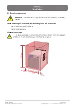
Ensure the underbench can support the product weight when full of water,
(Check the specifications in the main book and allow an extra 5-8kg when full. )
Before installing ensure the following have been provided at
the installation site:
•
Sufficient space in the cupboard to install all of the undersink units in accordance
with these Installation Instructions. Refer to technical specification for dimensions. If
required, make allowance for a booster heater. (Refer to the main book, for detailed
installation instructions).
•
A potable water supply connection with isolating valve inside the cupboard within
reach of the flexible braided hose and positioned so that the connection point and the
stop cock will not be obstructed when all the undersink units are installed.
•
For Zip HydroTap 160/125 &160/175 models, a 220-240Vac, 10A GPO will be
required. For Zip HydroTap 240/175 models, two 220-240Vac, 10A GPOs will be
required. (One GPO is for the Zip HydroTap and the other for the Booster heater).
NOTE: Check the cable lengths and outlet positions before proceeding.
•
A potable cold water supply with a minimum working pressure of 172kPa and a
maximum working pressure of 700kPa connected via an isolation valve.
•
For the mains pressure All-IN-ONE, both a hot and cold water supply will be required.
•
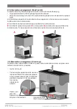
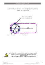
The undersink appliances must be mounted in upright positions as shown in the
diagrams.
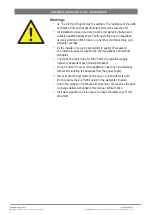
IMPORTANT!
Do not proceed with the installation if these
requirements are not met.
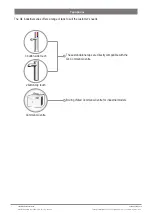
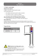
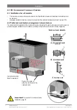
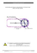
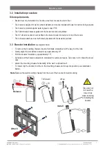
STEP 1-
Prepare and fit the Taps
Hole positioning:
Position the tap such that it dispenses into
the sink bowl with ample clearance for a cup or tea pot. Alternatively,
the tap could be mounted away from the sink using a Zip Font, avail-
able as an accessory.
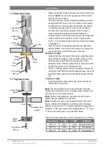
Apply a light smearing of silicon sealant
on the underside of the upper spacer to
ensure a watertight fi t.
For HydroTap and Mixer taps
cut a 35mm hole in the bench / sink top.
BENCH TOP
Ø35mm
HydroTap Tap
Mixer Tap
4-in-1
(If required)
NUT
LOWER RUBBER
WASHER
UPPER
RUBBER
WASHER
WASHER
BRAIDED
HOSE x 3
UPPER RUB-
BER WASHER
LOWER RUB-
BER WASHER
WASHER
NUT
White Hose
Ext. Mains
Blue band
Mixer IN
Red band
Mixer Out
O-RING
BASE
BLOCK
SPIDER
BASE
BLOCK
NUT
USB
CABLE
ALL
THREAD
ROD
NOTE: feed each of
the tubes and elec-
trical cable evenly in
between the legs of
the BASE BLOCK
SPIDER.
All-In-One Tap
(If required)
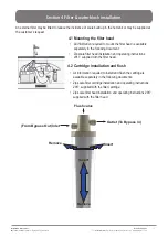
For AIO mains and vented Taps
Cut a 50mm hole in the bench / sink top.
NOTE: make sure the tap location will allow the nozzle to drain into the sink.
SINK TOP
50mm
ALL THREAD
ROD
STAINLESS
STEEL
WASHER
SPIDER
CLAMP
NUT
BLACK
PLASTIC
SPACER
NOTE: feed each of the three tubes and
electrical cable evenly in between the legs of
the SPIDER CLAMP when installing.
Fit the
STAINLESS STEEL
WASHER,
SPIDER CLAMP,
AND 6mm NUT.
6mm
NUT
SPIDER
CLAMP
Stainless
washer
Black plastic
spacer
35mm dia hole
Sink
O-RING
SINK TOP
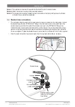
Fit the O-ring to the underside of the AIO tap
then pass all hoses through the 50mm hole.
Chiller
connection
BLUE
From
Mixer OUT
to Tap - Vented version only
Boiler
connection
RED
Blue ring on
RHS mains IN to
Mixer IN
White ring
on LHS to
Mains in
Tap
O ring Base
Clear tube to Vent
Parts supplied
Description
Tap options*
Side touch
3 button
Top touch
2 button
Command Centre and components
Duct kit
1 x Exhaust duct
1 x Mounting plate
2 x Outlet vent
1 x Inlet vent
1 x
Command Centre with
air and water filters
1 x Mains water
connection hose
1 x Booster inc.
connection hoses
(supplied with
240 models)
1 x User guide and
1 x Quick start guide
1 x Installation
instruction
Accessories
Description
Booster
(inc. connection
hoses)
Scale, taste & odour
filter
Scale filter
installation kit
(Filter not included).
Font, Integrated
Replacement
internal 0.2 micron
filter
Recommended
water block


