System Description & Relay Setup
System Description
The UPStealth® has 8 user-con
fi
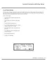
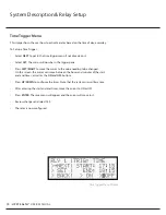
gurable relays that can trigger on a power failure, time of day, temperature,
fl
ash time, and at a
given battery capacity.
Each relay can be assigned to any of these triggers. Likewise, any relay can have more than one trigger type, in which case the
relay will trigger if any of the conditions occur.
When con
fi
guring a relay, each trigger is turned on separately for that relay. On factory default, all triggers for all relays are o
ff
.
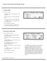
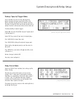
The left side is known as the “Common Panel”, and the right side is the “Trigger Panel”. These are divided by the vertical dashed
line. There is a unique trigger panel for each trigger option.
Settings such as temperature bounds
and times will be saved even when a
trigger is turned o
ff
.
The following information is common
to all applicable con
fi
guration screens.
Relay Setup and System Display
UPStealth
®
Interface
Common Panel
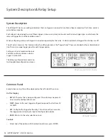
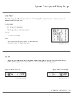
Except when saving, this will be displayed on the left side of the screen.
On This Display:
•
RLY (#):
The relay that is being con
fi
gured. This will always be present
on every relay con
fi
guration menu.
•
NEXT:
Moves to the next trigger con
fi
guration panel (Such as from AC
to TEMP).
•
SET:
Con
fi
gure the trigger for the relay. This will move the cursor into
the trigger panel, allowing for input of con
fi
guration options.
•
BACK:
Returns to the relay selection screen.
Controls:
•
Select one of the options with the directional arrows; press ENTER.
15
/
UPSTEALTH®
USER MANUAL


