PIM
The Power Interface Module (PIM) connects between the cabinet and the UPStealth®. The PIM allows the UPStealth® to be
removed or disconnected from the cabinet without removing the power from the cabinet. The UPStealth® connects to the PIM
with a plastic circular connector making it easy to disconnect the UPStealth® from the cabinet. The utility power is connected
to the AC INPUT Terminal Block and the cabinet is connected to the “AC TO THE CABINET” Terminal Block. With the PIM switch in
the “NORMAL” position, power to the cabinet comes through the UPStealth® and can provide battery backup. When the switch is
in the “BYPASS” position, power to the cabinet comes from the AC INPUT terminal block and the UPStealth® does not supply any
power to the cabinet. The PIM mounts to a rail in the cabinet with the mounting brackets supplied.
User Interfaces
There are two primary ways to directly interact with an installed UPStealth® while standing in front of the tra
ffi
c cabinet: the
front panel LCD display and keypad on the front of the Inverter/Controller or by connecting through the Ethernet port with a
laptop with the installed RTi Connect™ desktop application. Once connected through the Ethernet port, the technician can see
and manage the UPStealth® parameters menu. In addition, a technician can also connect to an installed UPStealth® remotely, as
long as the installed UPStealth® is connected to a network (see RTi Connect™ Manual).
Inverter/Controller User Display
The main user interface is the Inverter/Controller front panel keypad and the LCD Display. By moving the cursor on the display
with the “ENTER” key, you can highlight and select menu items. The arrow keys allow you to change the value of the item
selected.
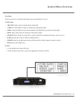
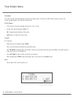
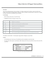
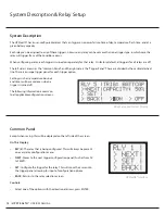
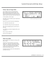
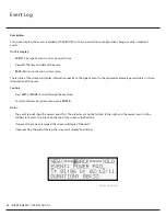
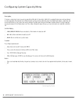
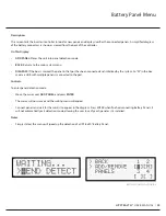
The LCD Display has several screens that allow the user to see all of the status information or set operating parameters of the
system. The following is an overview of each display:
Installation
UPSTEALTH®
USER MANUAL /
10


