background image

Ethernet Smart Cable

User Manual

UM020705-1012

Page 5 of 13

2. Use the Ethernet crossover cable supplied with the Ethernet Smart Cable to connect 

the Ethernet Smart Cable to the host PC’s Ethernet port.

3. Connect the 5 V DC power supply to the Ethernet Smart Cable power connector. As a 

result, the green PWR and RUN LEDs will illuminate. The green link LED on the 
Ethernet Smart Cable’s RJ-45 connector illuminates (see 

Figure 1

 on page 3), indicat-

ing a live Ethernet connection. The green activity LED on the Ethernet Smart Cable 
RJ-45 connector flickers, indicating network activity.

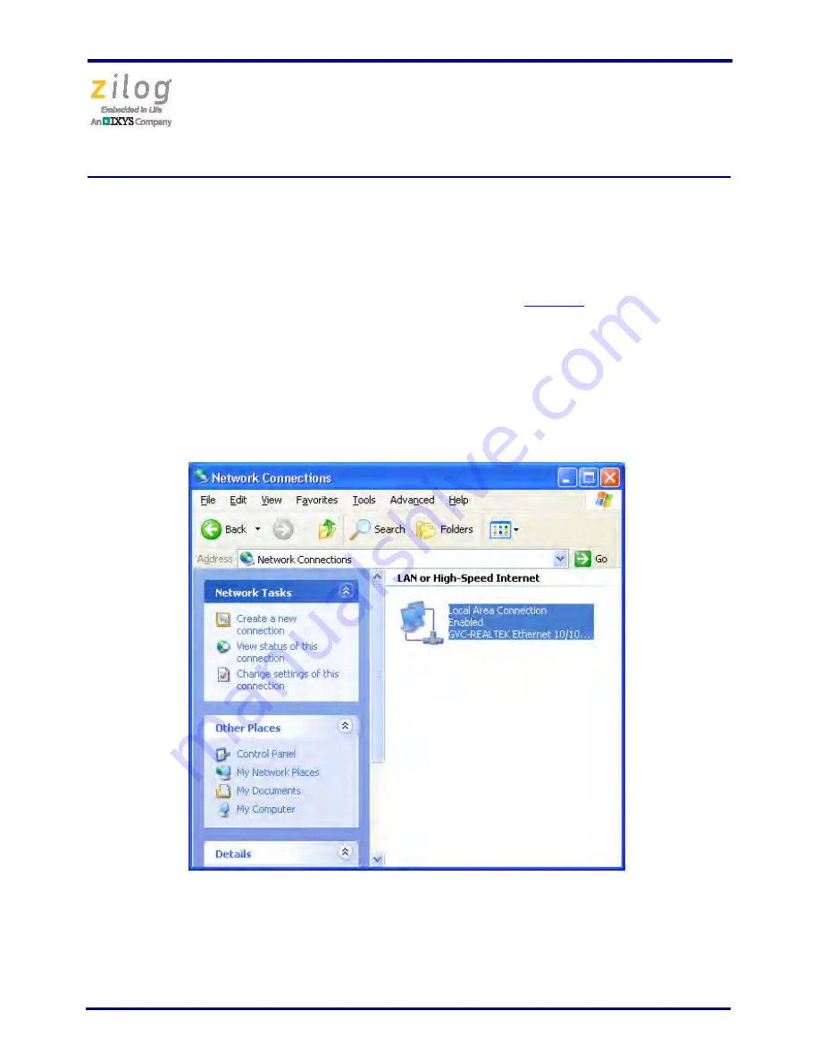
4. On the host PC, open the Windows Control Panel and double-click the 

Network and 

Internet Connections

 icon. The 

Network Connections

 dialog box will appear, as 

shown in Figure 2.

Figure 2. The Network Dialog

Summary of Contents for ZENETSC0100ZACG

Page 1: ...development kit Kit Contents To determine the contents of your kit refer to the Ethernet Smart Cable Packing List PAK0019 a paper insert included with your kit Software and Hardware Requirements The...

Page 2: ...DHCP server is available to assign an address Subnet mask 255 255 255 0 Gateway 192 168 1 254 No password required If you need to change the cable s factory default settings follow the steps describe...

Page 3: ...ct the Ethernet Smart Cable 1 Connect the Ethernet Smart Cable to an Ethernet connection 2 Connect the 5V DC power supply to the Ethernet Smart Cable power connector As a result the green PWR and RUN...

Page 4: ...sted in the Smart Cables Available list with the label on the bottom of the Ethernet Smart Cable 9 Click the OK button in the Project Settings window Your project is now configured to run with the new...

Page 5: ...the green PWR and RUN LEDs will illuminate The green link LED on the Ethernet Smart Cable s RJ 45 connector illuminates see Figure 1 on page 3 indicat ing a live Ethernet connection The green activit...

Page 6: ...ick the Local Area Con nection icon The Local Area Connection Status dialog box will appear as shown in Figure 3 6 In the Local Area Connection Status dialog box click the Properties button The Local...

Page 7: ...onnection uses the following items select the Internet Protocol TCP IP item to highlight it and click the Properties button see Figure 4 for an example The Internet Protocol TCP IP Properties dialog b...

Page 8: ...Cable 9 Click OK and restart the PC The PC is now ready to communicate with Ethernet Smart Cable via the ZDSII software The default IP address of the Ethernet Smart Cable unit is 192 168 1 50 Changing...

Page 9: ...art Cable s default settings 1 Obtain the Ethernet Smart Cable IP address 2 Open your web browser to the IP address located in Step 1 The Ethernet Smart Cable home page will appear as shown in Figure...

Page 10: ...point to the new IP address If the IP address remains at its previous setting the Ethernet Smart Cable home page will appear again displaying the changes you made Restoring the Ethernet Smart Cable F...

Page 11: ...Design for Debug Technical Note TN0035 or the Z8 Encore Design for Debug Technical Note TN0036 Using the Ethernet Smart Cable on ZDSII eZ80Acclaim Versions Earlier than 4 10 0 Observe the following p...

Page 12: ...ection ZDSII Cannot See the Ethernet Smart Cable If ZDSII cannot detect the Ethernet Smart Cable try the following workarounds Remove power from the Ethernet Smart Cable wait five seconds then reapply...

Page 13: ...onably expected to cause the failure of the life support device or system or to affect its safety or effectiveness Document Disclaimer 2012 by Zilog Inc All rights reserved Information in this publica...

Page 14: ...Mouser Electronics Authorized Distributor Click to View Pricing Inventory Delivery Lifecycle Information ZiLOG ZUSBOPTSC01ZACG ZENETSC0100ZACG...

Reviews: