


Z8018x
Family MPU User Manual
UM005004-0918
83
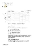
Interrupt Sources During RESET
Interrupt Vector Register (I)
All bits are reset to
0
. Because I =
0
locates the vector tables starting at
logical address
0000H
vectored interrupts (INT0 Mode 2, INT1, INT2,
and internal interrupts) overlap with fixed restart interrupts like RESET
(0), NMI (
0066H
), INT0 Mode 1 (
0038H
) and RST (
0000H
-
0038H
). The
vector table(s) are built elsewhere in memory and located on 256 byte
boundaries by reprogramming I with the LD I, A instruction.
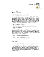
IL Register
Bits 7 - 5 are reset to
0
The IL Register can be programmed to locate the vector table for INT1,
INT2 and internal interrupts on 32-byte subboundaries within the 256
byte area specified by I.
IEF1, IEF2 Flags
Reset to
0
. Interrupts other than NMI and TRAP are disabled.
ITC Register
ITE0 set to 1. ITE1, ITE2 reset to
0
. INT0 can be enabled by the EI
instruction, which sets IEF1 to
1
. Enabling INT1 and INT2 also requires
that the ITE1 and ITE2 bits be respectively set to
1
by writing to ITC.
I/O Control Registers
Interrupt enable bits reset to
0
. All Z8X180 on-chip I/O (PRT, DMAC,
CSI/O, ASCI) interrupts are disabled and can be individually enabled by
writing to each I/O control register interrupt enable bit.
Summary of Contents for Z8018 Series
Page 1: ...www zilog com Z8018x Family MPU User Manual UM005004 0918...
Page 206: ...Z8018x Family MPU User Manual 192 UM005004 0918...
Page 220: ...Z8018x Family MPU User Manual 206 UM005004 0918...
Page 250: ...Z8018x Family MPU User Manual 236 UM005004 0918...
Page 260: ...Z8018x Family MPU User Manual 246 UM005004 0918...
Page 300: ...Z8018x Family MPU User Manual 286 UM005004 0918...
Page 306: ...Z8018x Family MPU User Manual 292 UM005004 0918...


