background image

Z8 Encore! XP F042A 8-Pin Development Kit

Quick Start Guide

QS005506-0111

Page 3 of 15

You can leave the adapter slot cover in place and plug in a standard computer equipment 
AC power cord (purchased separately) between the AC cord receptacle on the end of the 
power supply and an electrical outlet.

Setting Up the Development Board

The USB Smart Cable connects the target Z8 Encore! XP development board to a high-
speed or full-speed USB port on your ZDS II host system.

Always use a grounding strap to prevent damage resulting from electro-
static discharge (ESD).

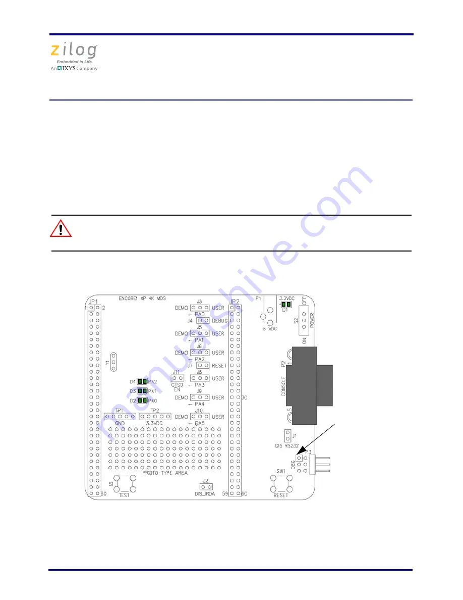
Figure 1 displays a simplified development board.

Figure 1. Z8 Encore! XP 8-Pin Development Board

Caution:

DBG Connector

Pin 1 (indicated 

by square)

Summary of Contents for Z8 Encore! XP

Page 1: ...for connecting the PC to Z8 Encore XP F042A Series Develop ment Board 5V DC Universal Power Supply Software on CD ROM Software requirements include Zilog Developer Studio II Zilog Developer Studio II...

Page 2: ...ew plug adapter into the slot until it snaps into place Table 1 Zilog Developer Studio II System Requirements Recommended Configuration Minimum Configuration Windows XP Professional SP3 or later Penti...

Page 3: ...d of the power supply and an electrical outlet Setting Up the Development Board The USB Smart Cable connects the target Z8 Encore XP development board to a high speed or full speed USB port on your ZD...

Page 4: ...dalone Demo mode ensure that the jumpers are set as follows J3 1 2 J4 OUT J5 1 2 J6 1 2 J7 OUT J8 1 2 J9 1 2 J10 1 2 J11 OUT To run the kit in DEBUG mode follow the steps as described in Getting Start...

Page 5: ...ersions of Windows 7 ZDS II Installation Directory device drivers USB x64 ZDS II Installation CD device drivers USB x64 6 Click Next The Windows Security dialog box appears 7 Select Install this drive...

Page 6: ...dware Wizard should activate automatically after connecting the Zilog USB device for the first time select No not at this time if asked to connect to Windows Update 2 Select Install from a list or spe...

Page 7: ...ribbon cable included to the USB Smart Cable six pin DBG connector as displayed in Figure 2 Attach the free end of the ribbon cable to the DBG connector on the target board Ensure that pin 1 on the r...

Page 8: ...drive and double click the launch exe file to launch the installer 2 DemoShield provides several installation options Select Install Zilog Developer Stu dio to install now You can install other softw...

Page 9: ...elopment Board on page 3 Do not apply power to the development board unless the USB Smart Cable is connected both to the host PC and to the development board s DBG port P3 3 Run the Zilog Developer St...

Page 10: ...04XP_8Pin_ledBlink src 6 Select the ledblink zdsproj file and click Open The initial Zilog Developer Stu dio II program screen appears see Figure 3 If you want to view the project source files double...

Page 11: ...en using the USB Smart Cable Click F1 for additional information on how to setup the debugger 8 Click OK 9 Click the Rebuild All icon to build the project Wait for the build to complete as indicated b...

Page 12: ...p 3 LED D2 PA0 is shared with the DBG pin Zilog does not recommend having the LED connected while connecting to the target or while in debug mode J3 should be OUT 13 Press the TEST push button to chan...

Page 13: ...code as described in Getting Started Using ZDSII on page 8 Verify that you have properly connected the USB Smart Cable to the host PC and the 8 pin development board as described in Setting Up the Dev...

Page 14: ...our host PC and console port P2 of the development board Set the communication settings in HyperTerminal to 57600 baud 8 bits no parity and one stop bit These settings are also noted in the main c fil...

Page 15: ...ailure to perform can be reasonably expected to cause the failure of the life support device or system or to affect its safety or effectiveness Document Disclaimer 2011 Zilog Inc All rights reserved I...

Reviews: