OWNER’S MANUAL - 19 - YF-48N A/0
REGULAR MAINTENANCE
For abnormal conditions that have been described in “Initial Diagnosis for an Abnormal Phenomenon” and “Abnormal
Status Shown by Indicator Lamps and Relevant Treatment Countermeasures”, the reasons should be found out in
accordance with the following sequence then the relevant treatment countermeasures should be determined.
Failure and Abnormity Examining
Power pilot lamp flashes, but the machine does not work.
Examine whether the manual switch is proper for use.
Examine whether there is
voltage on output of the
machine.
Replace
manual
switch.
Control cable
Examine whether
the cable is cut off.
Control parts failure
Contact to us for
repairing
Replace the
cable
The wire feeding circuit
is damaged Contact to
us for repairing
The wire feeder does not work.
Press the manual switch, examine whether there is air flow.
Examine whether there
is 24V voltage in both
ends of the motor.
Test and check the welding
gun switch to see
whether it works normally
Examine whether
the wire feeding
wheel is stuck.
The wire feeding
circuit is damaged
Replace the board
.
Remove the
dirt to keep
smooth
rotation.
The motor failure
Replace the motor
Examine whether
the control cable is
damaged.
.
Replace the
weld gun switch
.
Replace the control wire
or connect the wire.
Examine whether there
is DC 24V output of the
machine.
Examine whether the
plug has improper
contact.
If the control panel
is damaged,
replace it.
Yes
No
Yes
No
Yes
No
Yes
No
Yes
No
Yes
No
Yes
No
Yes
No
Yes
No
Summary of Contents for MIG-350
Page 1: ......
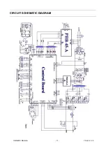
Page 12: ...OWNER S MANUAL 11 YF 48N A 0 CIRCUIT SCHEMATIC DIAGRAM...


