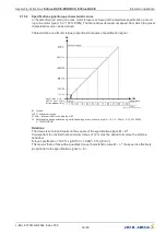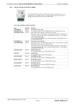
5.9
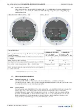
Analog input
“
E1
”
for setting speed
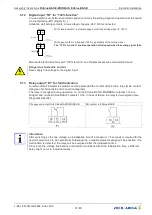
Depending on version for 0...10 V / 0...100 % PWM signal or for 10...0 V / 100...0 % PWM signal.
Connection to:
“
E1
”
/
“
GND
”
(Analog In 1).
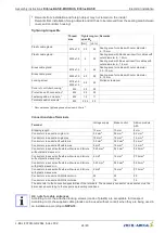
•
For fans with 0...10 V / 0...100 % PWM signal a 10 V signal or a sustained signal corresponds to
the maximum speed. If no signal is present, the fan stops.
•
For fans with 10...0 V / 100...0 % PWM signal a 10 V signal or a sustained signal corresponds to
fan stoppage. If no signal is present, the fan rotates with maximum speed.
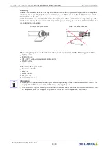
Danger due to electric current
•
Ensure correct polarity!
•
Never apply line voltage to analog inputs!
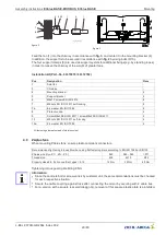
Possibilities for speed setting
•
Activation via external setting signal
0...10 V
(factory setting for E1).
•
Through external wiring with a resistor (499
Ω
/ 0.25 W) between terminals
“
E1
”
and
“
GND
”
parallel to the input signal, activation with a
0...20 mA
signal is possible (input programmed to 0...10 V).
•
Activation via external setting signal
4...20 mA
(see programming control
mode
“
E1
”
Function).
10V GND
E1
10 kΩ
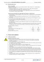
•
Speed setting by 10 k
Ω
potentiometer at terminals
“
+10 V
”
and
“
GND
”
pick-
off at terminals
“
E1
”
.
10V GND
E1
24V
PWM
f = 1...10 kHz
10 kΩ
1
0
V
G
N
D
E1
2
4
V
E1
E1
G
N
D
15...28 V
+
-
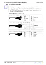
•
Control via external setting signal PWM.
CTE/AH(X)-L
GND
E1
PWM
(A4)
24V
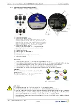
•
Connection to ZIEHL-ABEGG ventilation computer with PWM output
5.10
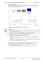
Output voltage
“
10 V
”
Voltage supply e.g. for speed setting by external potentiometer (PELV current source according to
EN 60204-1).
Connection:
“
10 V
”
-
“
GND
”
(max. load see Technical data und connection diagram).
It is not permissible to connect outputs of several devices to each other!
5.11
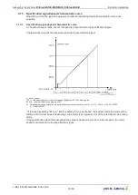
Output voltage
“
24 V
”
For external devices, a voltage supply is integrated (PELV current source according to EN 60204-1).
Connection:
“
24 V
”
-
“
GND
”
(max. load see Technical data und connection diagram).
During an overload or short-circuit, the control voltage (and thus the device) is disconnected .
Automatic start after elimination of the cause of error.
It is not permissible to connect outputs of several devices to each other!
Assembly instructions
ECblue BASIC-MODBUS, ECblue BASIC
Electrical installation
L-BAL-F079D-GB 2044 Index 002
Part.-No.
30/80

