


Start-up
•
Before
fi
rst-time start-up, check the following:
–
Installation and electrical connection have been prop-
erly completed?
–
Electrical connection carried out in accordance with
wiring diagram (wiring diagram in terminal box, for cable
version on cable or wall ring)
–
Turning direction corresponds to turning direction arrow
on fan blade or fan housing. The air
fl
ow direction or
turning direction determines the functionality of the fan,
not the motor rotation
fi
eld.
–
Is the protective earth connected?
–
Connection data complies with the speci
fi
cations on the
type plate.
–
Motor operating capacitor data (1~ motors) complies
with the speci
fi
cations on the type plate.
–
Safety equipment is in place (
→
Contact protection).
–
Temperature monitor/motor protection switch are
professionally connected and operating properly.
–
All leftover installation materials and other foreign mate-
rials have been removed from the fan cavity.
–
Cable gland is sealed (see
“
Installation
”
).
–
Do the installation position and the arrangement of the
condensation drain holes in the motor (if available)
correspond to each other (does not apply to protection
class IP55 fans)?
•
Start-up may only begin when all safety instructions have
been veri
fi
ed and any hazards have been ruled out.
•
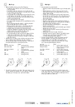
Check rotational direction/air feed direction: De
fi
nition of
the rotational direction according to pictures.
Series
Figure
RE, RG..P/S/R, RF
1
looking at rotor
RZ, RD..P/S/R
1
looking at motor shaft and
cable
RH, RG..A, RG..M
2
looking at rotor
RD..A/K
2
looking at motor shaft and
cable
GR
2
looking at rotor
RM, RR
3
looking at rotor
Fig. 1
Fig. 2
Fig. 3
•
Check for low vibration operation. Strong vibrations due to
erratic operation (unbalanced), e.g. caused by transporta-
tion damage or improper use, can lead to failure.
Devreye
•
al
ı
nmas
ı
ndan önce kontrol edin:
–
Montaj ve elektrik tesisat
ı
kurallara uygun olarak yap
ı
ld
ı
m
ı
?
–
Elektrik ba
ğ
lant
ı
s
ı
, devre
ş
emas
ı
uyar
ı
nca kuruldu
(terminal kutusunda devre
ş
emas
ı
, kablo veya duvar
halkas
ı
kablo tipinde)
–
Dön
üş
yön
ü
, fan kanad
ı
veya fan gövdesi
ü
zerindeki
dön
üş
yön
ü
ok i
ş
areti ile uyumlu. Fan
ı
n fonksiyonu için
hava sevk yön
ü
veya dön
üş
yön
ü
önemlidir, motorun
dönme alan
ı
de
ğ
il.
–
Koruyucu iletken ba
ğ
l
ı
.
–
Ba
ğ
lant
ı
verileri ile tip levhas
ı
ndaki bilgiler ört
üşü
yor.
– İş
letim kondansatörlerinin (1~ Motor) verileri, tip etiketi
ü
zerindeki veriler ile ört
üşü
yor mu?
–
Emniyet tertibatlar
ı
monte edildi mi (
→
Dokunmaya
kar
şı
koruma eleman
ı
).
–
Termik röle/motor koruma
ş
alteri kurallara uygun olarak
ba
ğ
land
ı
ve çal
ışı
yor mu?
–
Montaj art
ı
klar
ı
ve yabanc
ı
cisimler fan bölmesinden
temizlendi mi?
–
Kablo giri
ş
i s
ı
zd
ı
rmaz m
ı
(bkz.
“
Montaj
”
).
–
Montaj konumuna uygun kondens suyu delikleri (e
ğ
er
mevcutsa) aç
ı
k veya kapal
ı
m
ı
d
ı
r (IP55 koruma
s
ı
n
ı
f
ı
ndan fanlarda geçerli de
ğ
ildir)?
•
Devreye alma çal
ış
mas
ı
, ancak t
ü
m emniyet uyar
ı
lar
ı
kontrol edildikten ve herhangi bir tehlikenin mevcut
olmad
ığı
ndan emin olunduktan sonra yap
ı
lmal
ı
d
ı
r.
•
Dön
üş
yön
ü
n
ü
/hava sevk yön
ü
n
ü
kontrol edin: Dön
üş
yön
ü
, resimde gösterildi
ğ
i gibi olmal
ı
d
ı
r
yap
ı
tipi
Ş
ekil
RE, RG..P/S/R, RF
1
Rotora bak
ış
aç
ı
s
ı
nda
RZ, RD..P/S/R
1
Motor aks
ı
na ve kabloya
bak
ış
aç
ı
s
ı
nda
RH, RG..A, RG..M
2
Rotora bak
ış
aç
ı
s
ı
nda
RD..A/K
2
Motor aks
ı
na ve kabloya
bak
ış
aç
ı
s
ı
nda
GR
2
Rotora bak
ış
aç
ı
s
ı
nda
RM, RR
3
Rotora bak
ış
aç
ı
s
ı
nda
Fig. 1
Fig. 2
Fig. 3
•
Sessiz çal
ış
mas
ı
na dikkat edin. G
ü
r
ü
lt
ü
l
ü
çal
ış
madan
dolay
ı
g
ü
çl
ü
titre
ş
imler (dengesizlik) örn. ta
şı
ma hasarlar
ı
veya amaca uygun olmayan kullan
ı
m sebebiyle
ü
r
ü
n
ü
n
devre d
ışı
kalmas
ı
na neden olur.
8
T
ü
rkçe
english
00280351-GB-TR
L-BAL-005-TR-1939-Index
014