


Mounting
Do not loosen the impeller, fan or balancing weight.
Installation and electrical connection should only be carried
out by trained and qualified personnel.
Wear safety shoes and gloves for handling!
•
The system manufacturer or the machine builder is
responsible that the inherent installation and security infor-
mation are harmonized with the valid standard and guide-
lines (DIN EN ISO 12100 / 13857).
–
Design RE, RH, RM
, for attachment to
fi
xed motor
fl
ange: use property class 8.8 screws and provide with
suitable screw locking. Permissible tightening torque:
M4 = 2.1 Nm; M6 = 9.5 Nm; M10 = 40 Nm; M12 = 70
Nm; related to friction coef
fi
cient according to DIN EN
ISO 4014
µ
tot
= 0.12
–
Motor frame size
068
: comply with stated length of
thread engagement
–
Design RZ, RK without add on parts
, attachment to
axle ends according to manufacturers specifacions.
–
Design RG, RF, RD, RA:
fasten to the
fl
ange or
mounting bracket dependent on the housing mounting
form. Provide screwed connections with suitable screw
locking.
•
The following applies to all fan designs:
–
Avoid structural damage or stress with installation.
Flange and mounting bracket must be
fi
xed
fl
at on a
level surface.
–
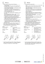
Ensure that the clearance (gap) "a" see
fi
g. between the
fan impeller and the stationary housing section is
constant. Distortion due to uneven surface may lead to
fan failure.
–
Protective measures must be taken against falling parts
when mounting with a hanging rotor.
–
In the case of a vertical motor axis, the respective lower
condensation drain hole must be open (does not apply
to protection class IP55 fans).
–
Motor frame size
068
: The condensation drain-holes
are attached dependent on the installation position or
application. Please supply information about this in the
product-speci
fi
c ordering texts. Make sure the conden-
sation drain-holes are not blocked!
–
Connect fan only to electrical circuits that can be
disconnected with an all-pole isolating switch.
–
Electrical connection according to connection diagram
a) in terminal box b) in cable model connection diagram
on cable or fan enclosure
–
Do not use metal compression-gland
fi
ttings with plastic terminal boxes. - Danger
of an electric shock if connection is not
made correctly!
–
Use a dummy plug seal for the compression-gland
fi
tting as well.
–
Only use lines which can guarantee a permanent seal
around the cable glands (pressure-resistant, dimension-
ally-stable, round-centred jacket; e.g. by means of
gusset
fi
lling)!
–
Depending on the type of cable gland, attach a water
drain sleeve or use a sealing compound.
–
Starting torque for screw on covers, Plastic version 1.3
Nm, Metal version 2.6 Nm
–
Secure fan connection cable with cable fasteners or
cable clips.
•
Depending on the model the motors
•
can be equipped with PTC's, internally connected thermal
contacts, lead-out thermal contacts or without thermal
protection.
Connect them as below:
Montaj
Pervane, vantilatör veya balans a
ğı
rl
ığı
n
ı
gev
ş
etme.
Montajı
ve elektrik bağlantısını yalnızca bırakın
eğitimli uzman personel
.
Koruyucu eldiven ve ayakkab
ı
giyin!
•
Sisteme ili
ş
kin montaj ve emniyet uyar
ı
lar
ı
n
ı
n geçerli
standartlar ve yönetmelikler (DIN EN ISO 12100 / 13857)
ile ayn
ı
do
ğ
rultuda olup olmamas
ı
, tamamen sistemin veya
tesisin
ü
reticisinin sorumlulu
ğ
undad
ı
r.
–
RE, RH, RM
yap
ı
tipine sahip fanlar
ı
sabit motor
fl
an
ş
lar
ı
na tespit etmek için 8.8 dayan
ı
kl
ı
l
ı
k s
ı
n
ı
f
ı
na
sahip c
ı
vatalar kullan
ı
n ve uygun bir c
ı
vata emniyeti
tak
ı
n. M
ü
saade edilen s
ı
kma torklar
ı
: M4 = 2,1 Nm; M6
= 9,5 Nm; M10 = 40 Nm; M12 = 70 Nm; DIN EN ISO
4014 standard
ı
na, s
ü
rt
ü
nme katsay
ı
s
ı
µ
µ
top
= 0,12
’
ye
uygun c
ı
vatalar ba
ğ
lam
ı
nda
–
Motor çerçevesi boyutu
068
belirtilen vidalama
derinli
ğ
ini dikkate al
ı
n.
–
Donat
ı
parçalar
ı
na sahip olmayan RZ, RK yap
ı
tipi
fanlar
, cihaz
ü
reticisinin verilerine göre bo
ş
aks uçlar
ı
na
tespitlenir
–
RG, RF, RD, RA yap
ı
tipi fan
, gövde yap
ı
tipine göre
fl
an
ş
a veya L tipi montaj braketine tespitlenir. C
ı
vata
ba
ğ
lant
ı
lar
ı
na uygun c
ı
vata emniyeti tak
ı
lm
ış
t
ı
r.
•
Fanlar
ı
n t
ü
m yap
ı
tipleri için
ş
u hususlar geçerlidir:
–
Gergin bir
ş
ekilde monte etmeyin. Flan
ş
ve L tipi montaj
braketi, ayn
ı
hizada olmal
ı
d
ı
r.
–
Resimde gösterilen
„
a
“
aral
ığı
n
ı
n her yerde e
ş
it
olmas
ı
na dikkat edin. D
ü
z olmayan dayanma y
ü
zeyi
nedeniyle olu
ş
an gerilme, pervanenin s
ü
rt
ü
nmesine ve
fan
ı
n devre d
ışı
kalmas
ı
na neden olabilir.
–
As
ı
l
ı
rotorla montaj yap
ı
l
ı
rken d
üş
en parçalara kar
şı
koruyucu önlemler al
ı
nmal
ı
d
ı
r.
–
Dikey motor aks
ı
nda, altta bulunan kondens suyu deli
ğ
i
aç
ı
lm
ış
olmal
ı
d
ı
r (Koruma s
ı
n
ı
f
ı
IP55 olan fanlar için
geçerli de
ğ
ildir).
–
Motor çerçevesi boyutu
068
: Kondens suyu delikleri,
montaj konumuna veya kullan
ı
m durumuna ba
ğ
l
ı
olarak
aç
ı
lmaktad
ı
r. Konuyla ilgili detayl
ı
bilgiler
ü
r
ü
ne özel
sipari
ş
metinlerinde verilmektedir. Kondens suyu
deliklerinin kapat
ı
lmamas
ı
na dikkat edin!
–
Cihaz, sadece t
ü
m kutuplardaki ak
ı
m
ı
kesen bir
ş
alter
ile kesilebilen bir ak
ı
m devresine ba
ğ
lanabilir.
–
Devre
ş
emas
ı
uyar
ı
nca elektrik ba
ğ
lant
ı
s
ı
a) Terminal
kutusunda b) Kablo tipi devre
ş
emas
ı
nda kabloda veya
fan gövdesinde
–
Plastik terminal kutular
ı
nda di
ş
li metal tapa
burçlar
ı
kullanmay
ı
n; yanl
ış
ba
ğ
lant
ı
da
yap
ı
lmas
ı
halinde elektrik çarpabilir!
–
Kör tapan
ı
n contas
ı
n
ı
di
ş
li tapa burcu için de kullan
ı
n.
–
Sadece vidal
ı
ba
ğ
lant
ı
lar
ı
nda s
ü
rekli bir yal
ı
tkanl
ı
k
temin eden kablolar kullan
ı
n (bas
ı
nç ve form dayan
ı
ml
ı
,
merkezi-yuvarlak k
ı
l
ı
f; örn. dolgu malzemesi arac
ı
l
ığı
ile)!
–
Kablo giri
ş
inin tipine ba
ğ
l
ı
olarak su tahliye dirse
ğ
i tak
ı
n
veya s
ı
zd
ı
rmazl
ı
k kiti kullan
ı
n.
–
Kapaktaki vidal
ı
ba
ğ
lant
ı
lar için s
ı
kma torklar
ı
: Plastik
model için 1,3 Nm, metal model için 2,6 Nm
–
Fan ba
ğ
lant
ı
kablosunu kablo ba
ğ
lar
ı
arac
ı
l
ığı
yla
koruma
ı
zgaras
ı
na veya motor desteklerine tespit edin.
•
Modele ba
ğ
l
ı
olarak motorlar
•
rezistörler, dahili olarak ba
ğ
lanm
ış
termik
ş
alterler, d
ış
ar
ı
al
ı
nm
ış
termik
ş
alterler ile veya termik korumalar olmadan
donat
ı
lm
ış
olabilir.
Bu koruma elemanlar
ı
ş
u
ş
ekilde ba
ğ
lanmal
ı
d
ı
r:
•
Rezistör, rezistör tetikleme
ü
nitesine.
5
T
ü
rkçe
english
00280351-GB-TR
L-BAL-005-TR-1939-Index
014