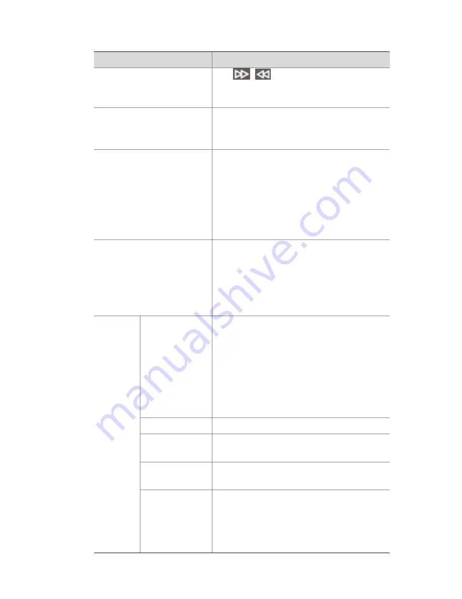
background image

7


Item


Function


and


Description


z


/

:


In


playback


mode,


rewind


or


forward


at


speed


when


the


playback


tool


bar


is


hidden.


OK


z


Confirm


the


operation.


z


In


playback


mode,


play


or


pause


when


the


playback


tool


bar


is


hidden.


USB


interface


USB2.0


(limited


to


1A)


used


for


connection


with


an


external


USB


mouse


or


storage


device.


Note:


Use


another


device


to


partition


and


format


a


USB


storage


device


into


FAT32


file


system


before


use.


POWER


ON/OFF


z


In


Soft


OFF


mode,


press


the


button


to


start


the


device.


z


In


normal


operation


mode,


press


the


button


to


turn


off


the


device.


Hold


the


button


for


at


least


3


seconds


to


switch


off


the


device.


Function


Buttons


Alphanumeric


Buttons


z


Used


to


enter


a


password,


number,


or


English


characters.


z


The


number


key


0


can


be


used


to


select


or


clear


check


boxes


in


the


list


box.


z


In


preview


mode,


used


to


switch


between


analog


channels


in


focus


panes.


SPACE


Used


to


enter


a


space.


DEL


Used


to


delete


characters


on


the


left


of


the


cursor.


F1


Used


to


switch


between


focus


areas


on


an


interface.


F2


z


Used


to


switch


between


menu


sub

tabs.


z


Used


to


capture


images


in


the


focus


pane


on


the


preview


and


playback


interface


(with


playback


toolbar


Summary of Contents for DVR200 series

Page 1: ...DVR200 Series Digital Video Recorders Quick Guide Manual Version P100 20140125...

Page 2: ...warranty of any kind express or implied Environmental Protection This product has been designed to comply with the requirements on environmental protection For the proper storage use and disposal of t...

Page 3: ...moisture z This installation should be made by a qualified service person and should conform to all the local codes z Please install blackouts equipment into the power supply circuit for convenient s...

Page 4: ...protection against harmful interference when the equipment is operated in a commercial environment This equipment generates uses and can radiate radio frequency energy and if not installed and used in...

Page 5: ...uropean Low Voltage Directive 2006 95 EC and EMC Directive 2004 108 EC WEEE Directive 2002 96 EC The product this manual refers to is covered by the Waste Electrical Electronic Equipment WEEE Directiv...

Page 6: ...nt of our company for help Otherwise we shall not be held liable for any consequence caused thereby z Make sure the device is sturdy and well grounded and meets heat dissipation and lightning protecti...

Page 7: ...Third Party Device 12 RS485 Serial Cables 12 Connecting to a PTZ via RS485 interface 13 Connecting to a third party device via RS485 interface 13 Connecting using an audio video cable 14 Connecting to...

Page 8: ...ce 19 Menu Structure 20 Initial Configuration 21 Quickly Adding IPC 27 Preview 30 Pane Toolbar on the Preview Interface 30 Preview Status 31 Right click Context Menu 32 Recording 33 Playback 34 Backup...

Page 9: ...and video playback on networks of various sizes eliminating the trouble of data sharing in conventional distributed storage applications 2 Mounting Installation Check Open the packing box and check th...

Page 10: ...ocess may varies according to conditions Install a hard disk as follows 1 Loosen the seven screws that secure the chassis cover and remove the cover 2 Fix four screws each half tight to the hard disk...

Page 11: ...isk into the hardy holes in the chassis backplane 6 Place the chassis in upright position and slide the screws to the other ends of the hardy holes in the direction indicated in the figure below 7 Tig...

Page 12: ...th screws The hard disk is completely installed Installing the Equipment Leave room of at least 30cm to the front and back and 10cm to the left and right sides of the equipment for ventilation Install...

Page 13: ...ing to actual conditions Front View 1 Status Indicators 2 DIRECTION OK 3 USB interface 4 Function Buttons 5 POWER ON OFF Indicators As shown in the front view the following table describes the indicat...

Page 14: ...nstantly on One hard disk at fault Blinking Several hard disks at fault or array rebuilt NET Network indicator Blue Constantly on Network properly connected CODEC Codec indicator Blue Blinking Signal...

Page 15: ...t the device z In normal operation mode press the button to turn off the device Hold the button for at least 3 seconds to switch off the device Function Buttons Alphanumeric Buttons z Used to enter a...

Page 16: ...rved SEQUENCE Used to start stop sequence display in preview mode BACKUP Used to enter the video backup interface in preview mode PLAYBACK Used to enter the video playback interface and display the pl...

Page 17: ...nterfaces No Item Description Function and Instructions AUDIO IN Analog audioinput NC single channel 2V P P 10K z DVR202 08 IN 8 z DVR202 04 IN 4 Connecting to an audio input device VIDEO IN Composite...

Page 18: ...nd cable DC POWER 12V DC 5A Connects to power adapter RS 232 485In terface Compatible with RS232 and RS485 serial ports and RJ45 connectors Connecting to RS232 or RS485 devices VGA Analog video output...

Page 19: ...terminal on the ALARM IN interface 2 Any terminal on the ALARM IN interface 3 Ground 4 Terminal G on ALARM IN interface 5 Normal open closed Boolean alarm input device 1 Alarm output circuit inside t...

Page 20: ...the RJ45 type of RS485 interface for connection with the PTZ and third party devices RS485 Serial Cables Twisted pair is recommended 22 28AWG insulating core wire preferably 24AWG or 26AWG can be used...

Page 21: ...e figure below for further connection 1 PTZ s RS485 control cable 2 PTZ s RS485 terminal 3 RJ45 s RS485 terminal 4 PTZ s RS485 terminal 5 RJ45 s RS485 terminal 6 Twisted pair Connecting to a third par...

Page 22: ...audio video cables from center to the two ends without interval and remove the cables in the opposite sequence Refer to the figure below to connect the required audio and video cables in accordance w...

Page 23: ...e for the audio output device 2 Connect a signal cable for the audio input device 3 4 Connect the common ground for audio and video input devices DVR202 04 IN z Push down Terminal I of the DVR202 04 I...

Page 24: ...deo input devices Connecting RS232 Serial and Network Cables Through an RS232 serial port connect the equipment to a serial device such as a PC For maintenance use the following serial cables take PCX...

Page 25: ...rounding resistance of less than 5 For specific requirements refer to the standards for the IEC61024 series As shown in the following figure connect one end of the ground cable to the ground terminal...

Page 26: ...running system processes so that the device enters power saving mode It is recommended that you disconnect the device from the power supply when the device is left idle for a long time Soft Off Using...

Page 27: ...hrough man machine and Web interfaces The photos herein are for illustration only and may vary according to actual conditions Man Machine Interface About the Interface Startup of the device takes a li...

Page 28: ...20 Menu Structure...

Page 29: ...want the startup wizard to guide you through fast configuration just skip the wizard and log in as admin Follow steps 3 to 5 for fast configuration 1 Determine whether to start wizard when device sta...

Page 30: ...22 3 Configure the network parameters a Click Network Configuration to enter the Network Configuration interface...

Page 31: ...IP address subnet mask and default gateway Normally set other network parameters to defaults c After configuration click OK Configuring eth0 card causes the system to restart service and then return t...

Page 32: ...ther system parameters to defaults c After configuration click OK Changing the management mode will restart the device 5 Configure storage parameters a Click Storage Configuration The Storage Configur...

Page 33: ...o virtualize an array before using it To do so select the array in the Virtualization Array box and click Virtualization NOTE Virtualization takes time After virtualization is complete virtualized in...

Page 34: ...26 d Configuring storage resources On the Storagetab configure storage resource parameters The following table lists the important parameters e Configuringstorageplans...

Page 35: ...an cannot overlap each other 6 After all configurations click Finish to save the settings and then you can perform various operations Quickly Adding IPC Only an admin user can add IPC Before adding th...

Page 36: ...are displayed below the list You can modify related parameters Important parameters are described in the following table Click Add to add the IPC Add IPCs in batches Select a number of our IPCs you w...

Page 37: ...ters are displayed below the list You can modify related parameters Important parameters are described in the following table Click Add to add the IPC Add IPCs in batches Select a number of third part...

Page 38: ...ick this button to enter the PTZ control interface in preview mode Manual record Records the live video in the current pane to a local destination Click the button again to stop manual recording Insta...

Page 39: ...t the tool bar Exit the toolbar for the current pane Preview Status On the preview screen video and alarm status of each channel can be identified by the identifier on the corresponding preview screen...

Page 40: ...occurs Mute This icon is shown in mute mode Manual record This icon is shown in manual record mode Right click Context Menu In the preview screen the right click context menu is shown in the followin...

Page 41: ...y Switch Monitor Switches between screens on a man machine interface Start Auto Switch In the preview screen poll switch between videos on various channels Video playback Enters the channel video play...

Page 42: ...within 5 minutes before the current time point Do as follows On the preview screen select the pane for video recording Click the Instant Playback icon to start playing Backup On the man machine interf...

Page 43: ...uery to display search results 3 Select video records you want to back up Select one or more video records you want to back up Click Backup to enter the backup interface CAUTION After selecting the ch...

Page 44: ...ect a folder 5 Backing up a video Click Backup to start video backup CAUTION During the backup process the progress bar will show backing up X Y x indicates the video records currently being backed up...

Page 45: ...xample camera 01 20121222000000 20121223103000 719885386 ts z Click Refresh to show the free and full capacities of the current partition on the USB storage device Web Interface 1 Start a Web browser...

Page 46: ...ng in to the web interface perform related configuration operations 7 Specifications For more information about technical specifications of the device refer to the datasheets Table 7 1 Technical Speci...

Page 47: ...xed bit rate Table 8 1 Storage Calculation Bit Rate Kbps Storage Used GB 256 2 900 512 5 801 768 8 701 1024 11 602 1536 17 402 2048 23 203 3072 34 805 4096 46 406 NOTE Please note that supplied values...

Page 48: ...BOM 3101C036...

Reviews: