


VITEK
FEATURES:
• 4, 8, 16, or 32 Channel HD-TVI / AHD / CVI / CVBS BNC Inputs Supporting up to
5MP Lite / 8 Mega Additional IP Camera Support of 2 ch. (VT-TR2HA410/
VT-TR8HA410), 4 ch. (VT-TR2HA810), 8 ch. (VT-TR2HA1620 / VT-TR2HA3280 /
VT-TR8HA820),
16 ch. (VT-TR2HA1620 / VT-TR8HA1620)
• IP Camera Support up to 4 MegaPixels (VT-TR5HA3280), 5 MegaPixels (VT-TR2HA
Series) and 8 MegaPixels (VT-TR8HA Series)
• HDMI (4K), VGA, and BNC Spot Video Output
• Simple plug and play, point-to-point connection from camera to DVR
• H.265 High Profile Compression (H.264 Compression on VT-TR5HA3280)
• 2-Way Audio
• PTZ Control over RS-485 / Control over Coax (CoC)
• 4 Alarm Inputs / 1 Output (4, 8, 16 Channel models) & 16 Alarm Inputs / 4 Outputs (32
Channel model)
• Pentaplex: Live Display / Record / Playback / Backup / Remote Access
• 1 Internal SATA2/SATA3 HDD Slot supporting up to 10TB (1 x 10TB HDD)
(VT-TR2HA410 / VT-TR2HA810) / 2 Internal SATA2/SATA3 HDD Slot supporting up to
20TB (2x10TB HDD) (VT-TR2HA1620 / VT-TR8HA820 / VT-TR8HA1620) / 8 Internal
SATA2/SATA3 HDD Slot Supporting up to 80TB (8 x10TB HDD) (VT-TR2HA3280,
VT-TR5HA3280)
• Applications for iOS & Android
• Remote Viewing over the Internet via Web Browser or LAN
• Mac OS® Client & CMS Central Management Software Included
• Supports both Dynamic and Static IP Addresses
• Control locally via USB Mouse or IR Remote control
• 3-year Warranty
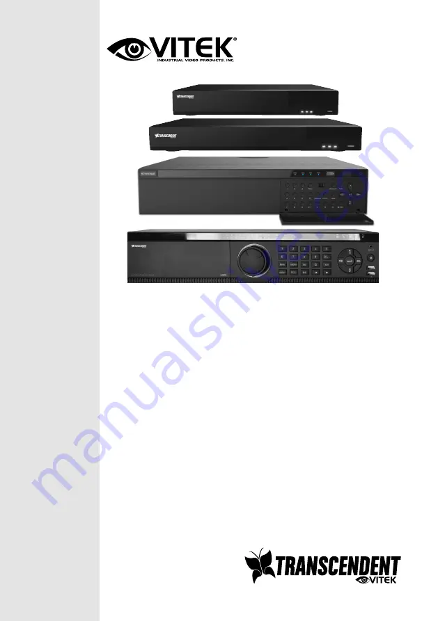
VT-TR2/5/8HA Series
Transcendent Series 4, 8, 16, or
32 Channel 2 / 8 MegaPixel 5-In-
1 HD-TVI / AHD / CVI / CVBS / IP
Digital Video Recorders


