Internal sensor fault
An internal sensor returned an invalid value.*
* These rare errors may indicate a hardware fault in the controller – please contact us!
Caution: There are no user-serviceable parts inside the controller.
Do not attempt to open the controller as this will void warranty!
CuSToMISIng your SeTTIngS
The MC1000SP stores a variety of operating settings in memory which may be modified by the user
via the provided serial programming cable. It should work with any personal computer which has
a USB port and serial communications software – the most common example being Hyperterminal
for Microsoft Windows. The motor controller can only be programmed when first powered up.
Once you start to drive, serial programming will be automatically disabled until the controller is
next turned on.
A USB to serial programming cable is supplied with the motor controller. If your computer doesn’t
recognise it when you first plug in, you may need to install the drivers. A copy may be downloaded
from: http://www.zeva.com.au/WinSerialdriver.zip
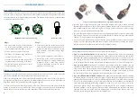
The following demonstrates how to set up Hyperterminal, but should be easily translated for other
serial communications software. The basic settings are 9600bps, 8-bit data, no parity, 1 stop bit,
no flow control. (Note that the COM port number may vary.)
hyperterminal settings windows
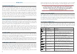
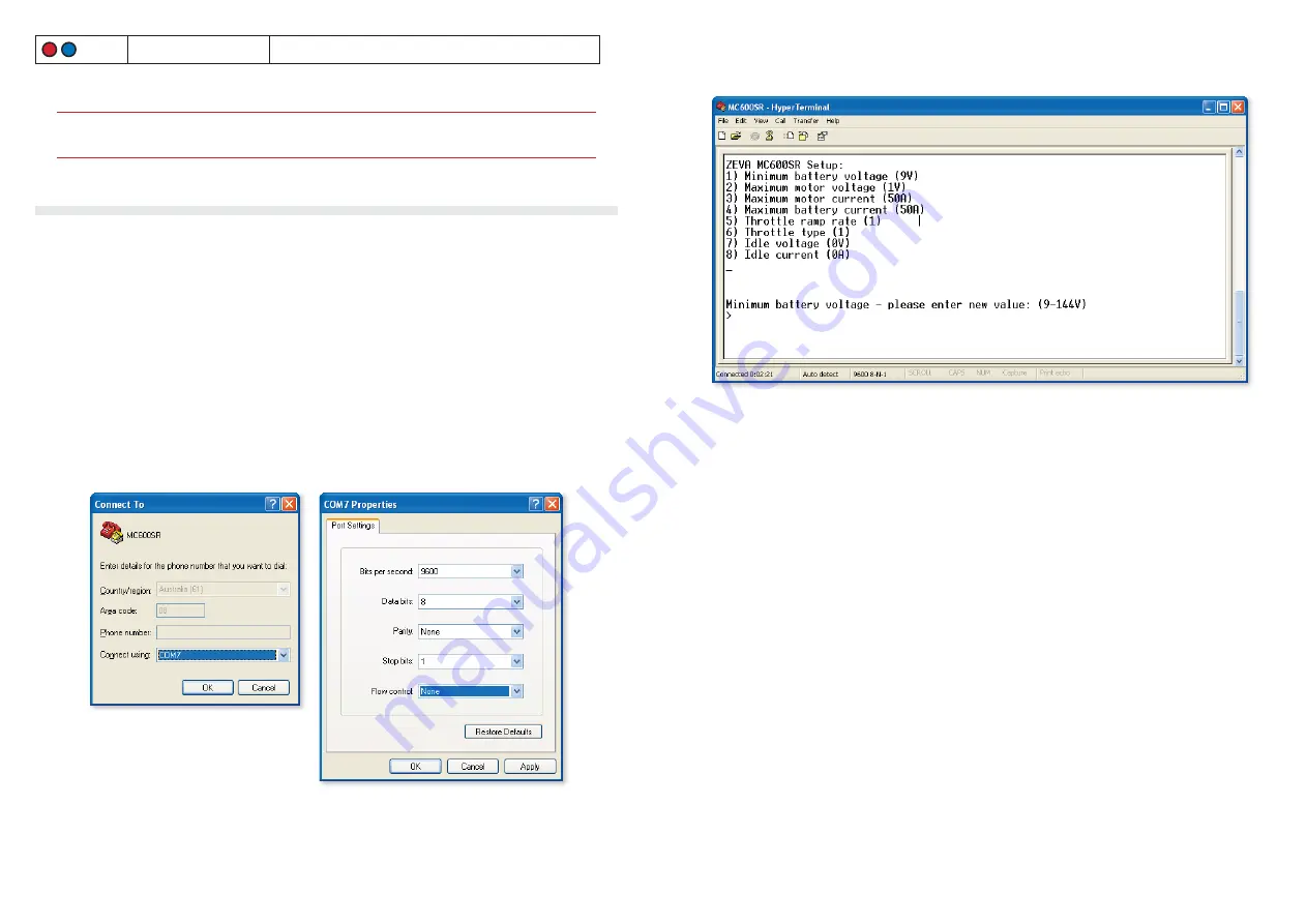
Once your connection window is up, press Escape and a list of available settings should appear
as per the following image. Press the appropriate number to select a parameter, then type the
new value and press Return to save. The acceptable parameter range is shown, and the controller
will automatically cap the parameter to this range if an invalid value is entered. At any time,
pressing Escape will return to the main menu. Once finished, simply unplug the programming
cable (settings are saved automatically).
hyperterminal Connection Window
Minimum battery voltage: This setting can be useful to avoid overworking or over-discharging
•
your battery, by setting it to whatever voltage represents a low state of charge (flat battery). Note
that this cannot replace a proper battery management system for protecting your cells!
Maximum motor voltage: If using a motor rated to a lower voltage than your battery pack, you
•
can use this setting to ensure that the motor controller will not overspeed the motor.
Maximum motor current: In vehicles with smaller motors, you may wish to reduce maximum
•
motor current in order to avoid damaging your motor from overcurrent. Most 6” or larger Series
DC motors will be fine with the maximum 600A setting.
Maximum battery current: If using small or weak batteries, you can adjust this setting to avoid
•
overworking your batteries. (This typically does not effect acceleration when setting off, but may
reduce high speed performance.)
Throttle ramp rate: This varies the rate at which the throttle is allowed to ramp up. A setting
•
of zero gives instant throttle response, with numbers 1–4 giving increasingly gentle throttle
ramps.
Throttle type: The MC1000SP supports three throttle types: (1) Three wire 0-5V analog plus
•
Enable (2) Two wire 0-5KΩ plus enable and (3) Hall Effect Pedal Assembly (HEPA). Please refer
to the Control Wiring: Throttle Device section for further details.
Idle voltage and current: These can be used to enable motor idling functionality. Be careful to
•
leave these as zero unless you are sure you need them, as it can cause the motor to run non-stop!
Refer to the Operation: Motor Idling section for more information.
11
10


