ConTrol WIrIng
Plug IdenTIfICaTIon
The MC1000SP uses two aviation-style screw-lock plugs for all control/low power connections,
one with 5 pins for the power input and status LED output connections, and the other with 6 pins
for the throttle and serial programming connections. The diagram below shows pin identifications
as viewed on the controller case.
Gnd
12V
B
G
R
5V
Gnd
ThrB
ThrA
Rx
Tx
LED
Identification of pins on control wiring plugs
Pins for remote led
Plug 1:
5V: Output power supply for throttle and/
•
or serial communications devices. Max
50mA output (internally fused, w/reset)
Gnd: Ground connection for throttle
•
Throttle A: First throttle input, usually the
•
analog level, 0-5V input
Throttle B: Second throttle input, either
•
enable switch or 2nd analog, 0-5V input
Tx/Rx: Transmit and receive pins for serial
•
communications, 5V TTL
Plug 2:
12V: Connect to a key-switched 12V supply
•
so the controller comes on when the key is
turned on. Often wired in parallel with your
main contactor. Maximum voltage range
8-18V input
Gnd: Connect to ground / vehicle chassis
•
R/G/B: Red, green and blue channels for
•
status LED output. 5V outputs, 2KΩ output
impedance (max 2.5mA). Gnd terminal
of LED is grounded to chassis (or shares
ground pin on same plug).
WIrIng uP The PlugS
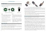
The plugs are opened using a small jewellers screwdriver to remove the screw on the side of the
rear shell, which then comes away with a small counterclockwise twist.
Feed wires through the back of the rear shell before attaching to the pins to ensure the case can
go together again after wires are attached. For reliable connections, be sure to “tin” (add solder to)
both the wires and the contacts before soldering them together.
The shell also has a cable stress relief clamp at the rear which can be fastened down to hold the
cables. If your cables are too small for the clamp to engage, you can wrap some insulation tape
around them to increase the diameter and ensure the clamp is able to hold them in place.
Plugs for control wiring: disassembled (left), wiring (middle), complete (right)
Since the logic wiring is necessarily quite close to the traction circuit power cables, to avoid
•
Electromagnetic Interference (EMI) it is best to use shielded cables, or twist wires (such as 12V
and Ground) together. Also avoid running logic wiring in parallel with power cables for long
distances, as it increases noise due to crosstalk.
The logic board only requires 200mA current, so as small as AWG28 wire may be used for the
•
power supply. However, if not enclosed in a shielded sheath, it is best to use larger cable around
18AWG+ for better mechanical strength/durability.
All control wiring is galvanically isolated from the power terminals. In most cases the control
•
wiring will share a common ground (the vehicle chassis) with your vehicle’s existing 12V system,
and the traction circuit should remain electrically isolated for safety.
ThroTTle devICe
The MC1000SP controller supports a variety of different throttle types.
Type 1, 0-5v hall effect throttle:
•
Any throttle device which outputs a 0-5V level representing
0-100% throttle may be used. Non-contact Hall Effect types are the best option due to their
reliability and virtually unlimited lifespan. They should have three wires to connect to Gnd, 5V
and Throttle A (0-5V level). The Throttle B pin should be connected to 5V through the enable
switch on the potbox (COM and NC terminals) for redundant safety in case of hall sensor fault.
Type 2, 2-wire 0-5KΩ:
•
Although not considered a great option due to their tendency to wear
out and become unreliable over time, legacy 2-wire resistive 0-5KΩ potboxes (such as the Curtis
PB-6) can be used. The two throttle wires connect to Throttle A and 5V (either polarity). The
enable switch should be wired between 5V and Throttle B, using the COM and NC terminals.
The controller will have to be programmed via serial interface for Throttle Type 2.
Type 3, hall effect Pedal assembly (hePa):
•
HEPA pedals are becoming the industry standard
for throttle devices in vehicles as they offer high reliability and safety through the use of dual
(redundant) hall effect sensors. A variety of different HEPA pedals are available, typically having
6 wires for two independent 3-wire hall effect type throttles. The MC1000SP was designed to
work with those providing dual analog outputs of around 0.7V–3.5V and 1.4V–4.2V. Use the
Gnd and 5V pins on Plug 2 to provide power to both sensors. The 0.7-3.5V signal connects to
Throttle A and the 1.4V-4.2V signal to Throttle B. With a HEPA throttle, the controller can detect
a throttle fault if any four of the wires are disconnected, or if either of the throttle sensors are
faulty. Be sure to configure the controller for Throttle Type 3.
7
6


