23
4
D
IGIT
S
TRAIN
G
AUGE
I
NPUT
O
PERATIONAL
M
ODES
G
AIN
S
ETTINGS
The system has three possible gain settings. The setting should be selected based on the
maximum expected output (sensitivity) from the transducer.
Links on Strain gauge Interface Board 023-14-07-003 (2
nd
from Cylindrical Housing End Cap)
Transducer Sensitivity
(mV/V)
Link
2
A
5
B
10
C
Fit the link on the strain gauge conditioning PCB according to the above table. The selected
sensitivity setting should be just greater than that of the transducer. The table below
illustrates some examples.
Transducer Sensitivity
(mV/V)
Display System Sensitivity
(mV/V)
1.852
2
2.050
5
3.580
5
4.815
5
6.326
10
C
ALIBRATION
In order to calibrate the system a reference calibrated measuring system and the Subsea
Display System, Command Console Interface are required (see Command Console Interface
section).
To calibrate the system:
1.
Reset calibration to default factory set condition.
METHOD:
COMMAND: ‘reset’
2.
With the transducer connected to the Subsea Display System and no load applied on the transducer, zero
the displayed value.
METHOD:
Make a note of the unscaled ADC reading. Use this as the zero value.
COMMAND: ‘pzeroXYYYY’, where X = sign and YYYY = value (e.g. ‘pzero+1234’)
3.
Put full scale or maximum load on transducer. Record reading from measuring system and reading from
the Subsea Display System.
Note:
Subsea Display must be set to show Nm.
CALCULATE:
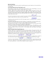
EXAMPLE CALCULATION:
Measured Load
(Nm)
X +8192 = Subsea
Display System
Full Scale
Measured Load = 400.0 Nm
(400.0/6864) x 8192 =
477.4
477.4 = Subsea Display
System Full Scale
Subsea Display
System Reading
(set to Nm)
Subsea Display System
Reading = 6864 (set to Nm)
4.
Program Subsea Display System full scale.
METHOD:
COMMAND: ‘pfsXYYYYY’, where X = sign and YYYYY = value (e.g. ‘pfs+477.4’)
Note: The value must be the 4 most significant digits and include a decimal point for example:
pfs+1.234
pfs+00.12
pfs-357.2
pfs-4562.
5.
Check reading against measuring system.

