


PREMIER QUATRO INSTALLATION MANUAL
Software Versions: PANEL 1.52 & LOOP CARD 2.0
Doc No. GLT.MAN-134
PAGE 31
Issue: 1.33 Author: GW/NJ Date: 14/1/2013
12. FIRE ALARM
12.1 INDICATIONS
A fire is indicated on the Quatro panel by the COMMON FIRE red LED. The zonal location of the fire is indicated by one of the zonal
indication red LEDs. Zonal indication is limited to the first 20 zones of the installation.
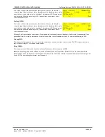
Fires in all zones will be indicated on the LCD. An example of the 4 line fire display is shown below:
Line 1 indicates the first zone in fire. In the example, the first alarm was in Zone 3.
Zone 3 is the Second Floor.
The 2nd line indicates the most recent zone in fire. The format is the same as line
1. The most recent fire occurred in Zone 5, which is the Fourth Floor.
Line 3 shows the total number of zones in fire and the total number of points /
devices in fire.
FIRST ALARM: Z003 - SECOND FLOOR
LAST ALARM : Z005 - FOURTH FLOOR
ZONES IN FIRE:004 POINTS IN FIRE:010
PRESS
◄
OR
►
TO SCROLL
All the points that are in the fire condition can be displayed in turn by using the
◄
or
►
keys to scroll through the fires. This
information is displayed on lines 3 and 4. For example:
In this example, line 3 indicates the 2nd point of the 10 points in fire. Point 2 was
triggered at the time 08:10. Point 2 is in Zone 17 (the Stair Well). Point 2 is an
Optical detector connected to Panel 2 and Loop 4. Its address is 124.
FIRST ALARM: Z003 - SECOND FLOOR
LAST ALARM : Z005 - FOURTH FLOOR
002/010-08:10 Z017
– STAIR WELL
Optical (2.4.124) - ROOM 101
Note that if the device in alarm is connected to one of the loops of the panel which is indicating the fire, the panel number is not
displayed in line 4, i.e. Optical ( 4.124 - ROOM 101).
12.2 OUTPUTS AND DELAYS
Following the indication of a fire, the panel will activate outputs (i.e. sounders and / or relays) according to the cause and effect
rules or ACTIONS that have been programmed (see Section 17). In certain circumstances, the activation of outputs may be delayed
whilst the fire is being investigated.
(a) Sounder Delays
If the operation of sounders has been delayed in one or more of the programmed ACTIONS, then this will be indicated by the
illumination of the DELAY ON LED (in the SOUNDER STATUS section of LEDs). When a fire has been indicated, the DELAY ON LED
remains lit until the longest sounder delay has expired.
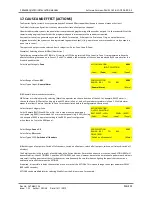
During a fire alarm it is possible to override all the sounder delays (at any access level) by pressing button F4, which is labelled [END
DELAY], as shown.
The [END DELAY] label is erased from the display when either the longest
sounder delay has expired or the sounder delay has been overridden by pressing
F4.
FIRST ALARM: Z003 - SECOND FLOOR
LAST ALARM : Z005 - FOURTH FLOOR
ZONES IN FIRE:004 POINTS IN FIRE:010
PRESS
◄
OR
►
TO SCROLL [END DELAY]
(b) Relay Output Delays
Relay outputs can also be delayed via the cause and effect actions. In this case, no LED is lit to indicate a delay (since this type of
output is not mandatory).
NOTE: It is possible to toggle delays on & off via the user menu. If the delay is not working as expected, check in the user menu if
the delays have been turned off. (If there are delays to sounders, the sounder delay LED will be lit when the delays are enabled.
Delays to relays do not turn on this LED)
12.3 CONTROLS
The panel contains the following mandatory controls. They can only be operated when the key on the front of the panel has been
turned clockwise from OFF to CONTROLS ENABLED. The CONTROLS ACTIVE LED indicates that the controls have been enabled.
START / STOP SOUNDERS
This control can be used by authorised personnel to stop or silence the sounders whilst the panel is in the fire alarm condition. This
control will alternately stop and start the sounders (i.e. silence and sound the alarms).


