


PREMIER QUATRO INSTALLATION MANUAL
Software Versions: PANEL 1.52 & LOOP CARD 2.0
Doc No. GLT.MAN-134
PAGE 28
Issue: 1.33 Author: GW/NJ Date: 14/1/2013
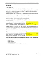
11.8 VIEWING DEVICE STATUS
To view the status of any loop device (point):
Turn the keyswitch clockwise to the Controls Enabled Position. The controls Active LED will light.
Press any key followed by the level 1 password (1111 is the default). Next select Point from the menu, followed by Show.
The information displayed is:- Loop, address, zone, point type, mode, analogue value & text label.
NB the same parameters are displayed as in Section 11.7 (Address Labels and Zones).
However, Level 1 password control does not allow the zone number and address label
to be changed.
For detectors, V is usually about 25 for clean air, and 55 during alarm. Non analogue
devices such as call points and I/O Units have a normal value of 16, and an alarm
value of 64. They will return a value of less than 8 to report a fault condition.
LOOP :<1> ADR :[105] ZONE:[016]
TYPE :Optical MODE :ENABLE V:025
TEXT : RESTAURANT -2ND FLOOR
[-]
[+]
[Exit]
The text labels displayed for each addressable point are:
Sounder, Input-Output, Ionisation, Zone, Optical, Opt-Heat, Heat and MCP. Each of these is known as the TYPE of a point or device.
NB Sounder can be a standard loop sounder or a sounder circuit controller for connecting conventional sounders to the loop. Zone
is an abbreviation for Zone Monitor Unit, for interfacing conventional detectors or call points to the loop. Opt-Heat is a combined
optical and heat detector. Heat can either be a fixed temperature heat detector or a high temperature heat detector.
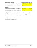
11.9 LOCATE OR VERIFY A DEVICE
It is possible to send commands to individual devices to turn on their alarm LED. This can be a very useful function when one wants
to locate a device or verify its address.
Turn the keyswitch clockwise to the Controls Enabled Position. The controls Active
LED will light. Press any key followed by the level 2 password (default 2222). Select
Points followed by Toggling LED. Select the loop and address of the point to be
checked.
LOOP :<001> ADR :[001] ZONE:001
TYPE :Optical MODE :ENABLE
TEXT : [3RD FLOOR WEST EXT]
[-]
[+]
[Exit]
The [-] and [+] commands can be used to decrement or increment the address of the point being searched for. If the device has a
panel controlled alarm LED it will be turned on immediately its address is selected. Scrolling to another device or exiting the menu
will automatically turn the LED off.
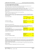
11.10 REMOTE OUTPUT
The remote output on a detector is used to switch on a connected remote indicator (LED). It is also used to tell the panel that a
detector has an associated sounder. Also known as a Platform sounder.
Turn the keyswitch clockwise to the Controls Enabled Position. The controls Active
LED will light. Press any key followed by the level 2 password (default 2222). Select
Point followed by Platform sounder. Change RMT from 'No' to 'Yes'.
LOOP :<001> ADR :[001] ZONE:001
TYPE :Optical MODE :ENABLE RMT: [YES]
TEXT : [3RD FLOOR WEST EXT]
[-]
[+]
[Exit]
11.11 PASSWORDS
As described earlier in this section, 2 passwords are required to view and set up the configuration on the Quatro panel. These are
required to increase the security of a site configuration.
(a) Level 1 or User Passwords (Default 1111)
Authorised users are allowed to view the panel’s configuration, status and event logs (see section 16). They can also disable (section
13) and test (section 14) the panel.
Each authorised user can be assigned his own 4-digit Level 1 password by the installation / commissioning engineer. The panel
permits up to 31 unique level 1 passwords, i.e. up to 31 people can have their own unique access to Level 1 data. It is recommended
that these passwords are assigned during the commissioning of the panel. Changes to these passwords at a later date will require a
further site visit by the installation engineer.
The Level 1 password can be changed as follows:
Turn the keyswitch clockwise to the Controls Enabled Position. The controls Active LED will light.
Press any key followed by the level 2 password (default is 2222). Press the
▼
key until “General” is highlighted. Select “General” and


