background image

SIMPLICITY PLUS INSTALLATION MANUAL


Approved Document No: GLT.MAN-107 


PAGE 10


Issue 3.16         Author: NRPJ      Date: 21/09/2017 

6.2 FIRST FIX 

6.2.1 MOUNTING THE FIRE ALARM PANEL 

The Simplicity comes with many cable entry holes. If another entry hole is required, it is strongly recommended that the 
panels door be removed to avoid accidental damage. Also, the termination and Power Supply PCBs should be removed 
and stored in a safe place. This would also help while fixing the back box to the wall. 

6.2.2 FIXING THE BACK BOX TO THE WALL 


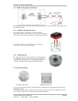
Figure 2:  Plan view inside the enclosure without PCBs. Side view for surface installation. 
Fix the enclosure to the wall using the three mounting holes provided. 
Check the build & condition of the wall to decide a suitable screw fixing.  
The mounting holes are designed for No 8 roundhead or countersunk woodscrews (or similar). 
Remove any debris from the enclosure.  
Take care not to damage the FACP during installation. 

6.2.3 PLANNING CABLE ENTRY 

Fig.2 above shows the location of the cable entries to facilitate planning of wiring (home runs) to be brought to the panel.  
The grommets can be easily removed by a push from inside the control panel box. 
If a grommet is removed, fill the hole with a brass cable gland.  If any knockout is removed, but subsequently not used, it 
should be covered up. 
The 230Va.c. Mains cable must be fed into the enclosure via one of the cable entries at the top right corner of the back 
box.  (Refer to “Connecting the Mains” on Following Page). 

Summary of Contents for Simplicity Plus 64

Page 1: ...SIMPLICITY PLUS INSTALLATION MANUAL Approved Document No GLT MAN 107 Issue 3 16 Author NRPJ Date 21 09 2017 ONE OR TWO LOOP ANALOGUE ADDRESSABLE FIRE ALARM CONTROL PANEL INSTALLATION MANUAL ...

Page 2: ...Control Module 15 7 1 6 ZAZM MI Conventional Zone Module 16 7 1 7 Xtratone Sounder Sounder Flasher 16 7 1 8 Sandwich Sounder 16 7 1 9 Remote LED Indicator 16 7 1 10 Isolator Base 17 7 2 MAXIMUM LOOP LENGTH RECOMMENDATIONS 17 7 3 SETTING THE DEVICE ADDRESS DETECTORS CALL POINTS SOUNDERS 17 7 4 ADDRESS ZONE TABLE 18 8 SOUNDERS 19 8 1 ADDRESSABLE SOUNDERS 19 8 2 SANDWICH SOUNDER BASES DETECTOR TRIGGE...

Page 3: ...E DISABLEMENTS DURING A FIRE ALARM CONDITION 36 17 DISABLEMENT 37 17 1 ZONE DISABLEMENT 37 17 2 TO PROGRAMME ZONE OR SOUNDERS AS DISABLED 37 17 3 DEVICE DISABLEMENT 37 17 4 VIEWING DISABLEMENTS 38 17 4 1 VIEWING DISABLED ZONES 38 17 4 2 VIEWING DISABLED DEVICES 38 18 TEST MODE 39 18 1 WHY USE TEST MODE 39 18 2 TO PROGRAMME ZONE IN TEST MODE 39 19 GENERAL FAULT FINDING 40 19 1 COMMON FAULT 40 19 2 ...

Page 4: ...tic Always handle PCBs by their sides and avoid touching the legs of any components Keep the PCBs away from damp dirty areas e g in a small cardboard box 1 2 SAFETY PRECAUTIONS DURING NORMAL OPERATION OF PANEL NOTE When the Simplicity Plus panel is operating normally i e not being tended by service personnel the access door must be closed and locked After locking the key MUST be removed and ONLY h...

Page 5: ...uirements The Simplicity Plus also has the following ancillary functions not required by the Standard Class Change Input to allow remote activation of sounders Serial repeater output RS485 Serial Output Port RS232 2 2 POWER SUPPLY SECTION The Simplicity Plus Fire Alarm Panels Power Supply Equipment PSE Has been designed to EN54 4 1998 A1 A2 Fire Detection Fire Alarm Systems Power Supply Equipment ...

Page 6: ...le individual devices or whole zones Detector LED sounder can be operated from the menu to help identify devices Panel software version can be viewed through menu The 64 could be upgraded to a 126 by changing the CPU card The Old version Simplicity 126 could also be upgraded to a Simplicity Plus by replacing the CPU card Version 3 Simplicity plus Metal box Version 3 of the Simplicity panel s main ...

Page 7: ...N PANEL LOOP ADDRESS LOOP ADDRESS DEVICE LABEL 20 CHARACTERS for device PLUS 20 Characters for the ZONE 20 CHARACTERS PREALARM PRESET 45 PRESET 45 DETECTOR SENSITIVITY PRESET 55 PRESET 55 ZONE ALLOCATION PROGRAMMABLE SET BY DEVICE ADDRESS PROGRAMMING FULL PROGRAMMABILITY COMMON OR ZONAL OPERATION ONLY EVENT LOG YES 4096 EVENTS YES 2048 EVENTS While all options are programmable on our Premier AL sy...

Page 8: ...s in a step by step manner the procedure for the basic design and installation of the Simplicity Plus Range of Fire Alarm Control Panels It gives detailed instructions on how to use all the features on this fire alarm panel For operational and maintenance information please refer to document GLT MAN 108 USER MANUAL MAINTENANCE GUIDE LOG BOOK It also contains a System set up table and Installation ...

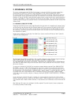
Page 9: ...81 to 96 Zone 7 Addresses 97 to 112 Zone 1 Addresses 1 to 16 First Zone 4 Addresses 49 to 64 Zone 5 Addresses 65 to 80 Zone 1 Addresses 1 to 16 Ground Zone 2 Addresses 17 to 32 Zone 3 Addresses 33 to 48 Zone 1 Addresses 1 to 16 The advantage of this method of zone allocation is that it simplifies the panel set up by eliminating a programming stage Note that a Simplicity 64 can only have 4 zones so...

Page 10: ...S5839 Pt1 2013 Clause 26 are Standard fire resisting cable to PH30 classification of EN 50200 Enhanced fire resisting cable to PH120 classification of EN 50200 Note that all cables should be at least 1mm 2 cross section On the Simplicity Panel the general recommendation would be to use standard fire resistant cable such as Zeta Alarm Systems Fire Defence Cable Firetuff FP200 or any equivalent Thes...

Page 11: ...wall using the three mounting holes provided Check the build condition of the wall to decide a suitable screw fixing The mounting holes are designed for No 8 roundhead or countersunk woodscrews or similar Remove any debris from the enclosure Take care not to damage the FACP during installation 6 2 3 PLANNING CABLE ENTRY Fig 2 above shows the location of the cable entries to facilitate planning of ...

Page 12: ...should be passed twice through the provided ferrite This is made easier by removing the outer insulation The cable is then connected to the Live Earth and Neutral connections marked on the power supply cage The Mains is protected by an INTERNAL fuse on the PSU cage This fuse is not user replaceable The incoming mains cable should be kept separate from the addressable loop cables to help minimise m...

Page 13: ...e of Battery 1 to the black battery charger lead Connect the ve of Battery 2 to the red battery charger lead The ve of the first battery is connected to the ve of the second battery using the FUSED link wire supplied When fitting the batteries take care not to damage the temperature monitoring thermistor next to the charger lead connections This is used to prevent overcharging the batteries in hig...

Page 14: ...solator fitted This is to prevent a short circuit fault in one zone affecting another zone Note that some Devices for example a sounder controller circuit may require a separate 24 volt supply to operate A maximum of 32 loop powered addressable sounders or sounder bases are permitted on a loop Short circuit isolators should be used to prevent losing the whole loop in the event of a single short ci...

Page 15: ...ut terminal on the call point The following terminals are used for connecting the call point 2 x Negative in terminals note if you only connect to the negative in terminals then the isolator is bypassed 1 x Positive in terminal 1 x Positive out terminal 1 x Negative out terminal note if used puts the isolator in circuit 1 x Earth terminal used to connect the cable screen 7 1 2 MKII detectors All t...

Page 16: ...nd of line resistor value is 20KΩ and the trigger resistor value is 1K 7 1 5 ZASC MI Sounder Control Module The ZASC requires a external 24vdc power supply as shown in the above diagram The EOL for the sounder circuit is 10KΩ When using the ZASC make sure the PSU being used has a fault output relay so that in the event of a power supply fault it is reported to the control panel Note All Power Supp...

Page 17: ...rminals in the back box of the device Please refer to the above diagram 7 1 8 Sandwich Sounder The sandwich sounder has no wiring to connect as it just clips straight on to a standard base It will run as a platform sounder using no address it is controlled by the detector fitted to it It can also be given an address via the handheld programming tool making it an addressable sounder 7 1 9 Remote LE...

Page 18: ...A using 1 5mm cable can have a maximum loop run of 1250m end to end 7 3 SETTING THE DEVICE ADDRESS DETECTORS CALL POINTS SOUNDERS The device address is set with a dip switch on the rear of the device 1 7 6 5 4 3 2 8 ON The address setting is binary with the ON position being binary 0 and the OFF position being binary 1 On a Simplicity system a MKII Protocol device must ALWAYS have Switch 8 set to ...

Page 19: ... ON ON OFF ON ON 59 OFF OFF ON OFF OFF OFF ON 102 ON OFF OFF ON ON OFF OFF 17 OFF ON ON ON OFF ON ON 60 ON ON OFF OFF OFF OFF ON 103 OFF OFF OFF ON ON OFF OFF 18 ON OFF ON ON OFF ON ON 61 OFF ON OFF OFF OFF OFF ON 104 ON ON ON OFF ON OFF OFF 19 OFF OFF ON ON OFF ON ON 62 ON OFF OFF OFF OFF OFF ON 105 OFF ON ON OFF ON OFF OFF 20 ON ON OFF ON OFF ON ON 63 OFF OFF OFF OFF OFF OFF ON 106 ON OFF ON OFF...

Page 20: ...d it might be possible to speed up the sounder base start stop time See CONFIGURING ASSOCIATED SOUNDERS section 8 3 SANDWICH SOUNDER BASES ADDRESSD MODE The sandwich sounder can be given an address with the hand held programming tool The sunder needs to be given a separate address to the detector The advantage is that the sounder is seen by the panel so can be monitored by the panel 8 4 ADDRESSABL...

Page 21: ...y take a few seconds There are 2 methods to speed up the stop times of these sounders 1 For ease of functional checking during installation the simplicity panel assumes that every detector found during the loop configuration has an associated sounder base This allows every sounder to run If the system uses associated sounders on some addresses then the addresses with no sounder should have the ass...

Page 22: ...m condition It can be connected to emergency lights local fire fighting equipment such as sprinkler systems magnetic door holders air conditioning shut off etc Extra alarm relays can be achieved by fitting extra I O Interfaces to the addressable loop ZAIO MI Fault Output FAULT This is a SELV volt free relay that operates in the Fault condition It is Normally Energised which ensures it can give a f...

Page 23: ...INATING THE WIRING Figure 6 Cable connections All cables entering the enclosure should have cable glands which will prevent unwanted openings in the enclosure The Addressable Loop circuits should be connected to the appropriate connector block on the Termination PCB All cable screens should be terminated at the brass earthing strip as shown in Figure 6 ...

Page 24: ...supports up to 4 repeaters Connections See Section 21 for the serial repeater connections 11 2 SERIAL PRINTER CONNECTION The Simplicity has an RS232 Serial output that transmits panel events as they occur It can connect to the Zeta TCP IP Interface Ask distributor for more details or a serial printer The recommended printer is an Epson LQ300 II The serial port on the Simplicity is configured to th...

Page 25: ...enu 2 In this menu there are options to Configure the loops to edit each device and to configure the system options The arrow in the bottom left hand corner shows that pressing PREVIOUS button will return to Configuration Menu 1 Configuration Menu 2 4 Configure Loops 5 Edit Device 6 Config System 4 Press button 4 to configure the loop The panel displays configuration in progress Please wait It wil...

Page 26: ...f every detector has a sounder base or if most of the detectors have a sounder base this speed up operation will have little or no effect 1 Press enter NEXT followed by 369 to enter Configuration Menu 2 Select option 5 to edit device status Select a detector that does NOT have a sounder base attached 2 Press the Disablement SELECT button The sounder symbol turns off to show that this detector no l...

Page 27: ...h area The minimum number of addresses per zone is 2 Zone Boundaries Zone 1 001 010 ENTER to Change All 8 zones do not need to be use i e the 126 device version could be configured as 6 zones of 21 devices leaving zones 7 8 void NOTE Zones 1 to 7 must have a minimum of 2 addresses per zone Zone Boundaries Zone 2 011 032 ENTER to Change 12 8 CHANGING THE ALARM RESPONSE SOUNDERS By Default the Simpl...

Page 28: ... common or Zonal operation then press enter Sounder Operation Sounder Bases Common ENTER to Confirm 12 9 CHANGING THE ALARM RESPONSE I O UNITS Because a system could have several I O units each reacting to different types of events the simplicity system adopts the following method for configuring I O units 1 Select a default I O unit operation This is done from the Alarm Operation Menu This will t...

Page 29: ...go to configuration menu 2 Select Edit Device Scroll to the required Address Press Button I for Input to cycle through the different Triggering Options of I O configuration The different options are Letter Description Use A AUTOMATIC ALARM I O signals Detector alarm when operated Default setting Used when device being monitored is Automatically triggered M MANUAL CALL POINT ALARM I O signals a MCP...

Page 30: ...anguage Bank 2 English Hungarian Serbian Lithuanian Configuration Menu 2 4 Configure Loops 5 Edit Device 6 Config System 12 11 SOFTWARE VERSIONS From Configuration menu 2 Select configure system option 6 Then from the Misc Settings menu select option 2 Version Info Misc Settings 1 Language 4 Mode 2 Version 5 Name 3 Protocol 6 Tone The panel will display the software versions in its two Microcontro...

Page 31: ...ol From Configuration menu 2 Select configure system option 6 Then from the Misc Settings menu select option 3 Protocol Press Prev Next to select Standard or Fyreye Mk2 protocol and then press ENTER NOTE The Factory Default option will reset the panel to the Fyreye Mk II Protocol If your system is running the standard Zeta protocol devices then you will need to change the protocol as described abo...

Page 32: ...tector stays in alarm by the end of the verification delay the system will go into full alarm If another detector WITHOUT verification setting or a call point goes into alarm the panel will go straight into full alarm With this method of operation a cooking alarm in one apartment will alarm locally giving the apartment occupants a chance to clear the smoke before the whole building is evacuated Al...

Page 33: ...nse back to all common resets system timers 4 Devices Clears device information from memory and clears device label device configuration 6 All Performs 2 3 4 in one operation When you select to reset a section the panel will display something like Clear Event Log ENTER to Continue Press enter to confirm or cancel to abort the action The panel will then warn that this action cannot be undone Clear ...

Page 34: ...s not to ring any sounders 2 MCP Choose MCP to cause zonal alarm or common alarm for sounders 3 SOUNDER Select if the sounders have a zonal to common time out when triggered zonally 4 Bases Select if associated sounder bases work common or zonal 5 I O Select default I O type 6 Relay Chose if the on board fire relay operates for all alarms detector alarms only or manual call point alarms only 4 Tim...

Page 35: ...he following messages Optical Changed Analog 25 Fault Fl 3 Bedroom 303 Zone 01 Ad 016 FAULT MEANING Changed The device had been changed with one of a different type since last configuration The message will flash between Changed and the new type of device seen e g Ion Missing The device is not communicating i e removed damaged or Address setting changed Side A Only There is a break in the cable an...

Page 36: ...and the Zone loop and address if appropriate Next Previous buttons will cycle through the list Event 173 25 01 2007 17 21 Device Alarm Zone 01 Lp 1 Ad 013 System The Simplicity also records other non critical items such as keyswitch turned on etc These can be used to help determine the chain of actions before or after an event The type of events recorded are Power On Startup Panel Reset Evacuate K...

Page 37: ...ms in the second zone that went into alarm etc To view the alarms chronologically the event log must be used FIRE First Z01 2 of 2 Last Z02 Kitchen Zone 02 Ad 017 16 2 VIEWING FAULTS DURING A FIRE ALARM CONDITION In the event of multiple alarms and multiple faults on the system at the same time the LCD screen will give priority to alarm events The screen will show the first alarm and the Prev Next...

Page 38: ...d and the Zone or Sounder LED will come on steady along with the GENERAL DISABLEMENT LED This section is now disabled NOTE Call points in this zone will also be disabled To keep the call points functioning disable the detectors in that zone individually as devices see 17 3 Zone Disablement Zone 3 Zone Disabled Disabled Devices 0 If more than one zone or sounder needs to be disabled then press DISA...

Page 39: ...he screen will show Zone Disablement Zone 1 Zone Enabled Disabled Devices 0 If a zone is disabled the screen will show Zone Disablement Zone 1 Zone Disabled Disabled Devices 0 If there are one or more disabled devices in a zone the screen will show this by the number of Single Devices as follow TIP a quick way to enable several disabled devices is to disable the zone in which these devices are loc...

Page 40: ...his zone can now be tested with smoke spray The Detector will light its LED until the smoke clears then it will reset The Sounders the fire relay are not operated during test mode Once testing of that zone is completed press TEST FUNCTION SELECT button to move to another Zone or turn the control key switch to off position to exit test mode Select Zone to Test Zone 1 Test Active Zone 1 18 3 TO PROG...

Page 41: ... doubt contact your supplier If the wiring polarity is correct check that there is no cable break on the loop If there is a break the panel will report the break after 60 seconds or so and inside the panel the LOOP POWERED LEDS on the termination PCB will alternate on off Some devices take a few seconds to power up so may show as missing during the repeated Power Down Power Up cycle that occurs du...

Page 42: ...enomena This will result in the panel attempting to correct itself Should this fault occur the System Fault LED General Fault LED General Fault relay and fault internal buzzer will be constantly active until the control keyswitch is turned from off position to control enable position This should cause this fault condition to reset If not consult your supplier 19 8 PRE ALARM This is not a fault con...

Page 43: ...evices wait for the zone fault LED check the addresses in that zone then there is probably a short circuit on the loop look for isolators lit Yellow or flashing The missing devices should give an indication of the section with the break Investigate that section as per the dead short circuit fault tracking method as described above If there are no missing devices then there is probably a simple bre...

Page 44: ... 13 2 10 20 Fyreye Addressable Beam Detector 5 50m ZT BEAM SMM B 5 7 9 16 32 Sandwich Sounder Base MKII SSB 0 6 N a 7 5 32 64 Zeta Addressable Maxitone Sounder MKII AMT 0 6 N a 7 0 32 64 Zeta Addressable Maxitone Sounder flasher MKII AMTF 0 6 N a 10 6 24 48 Zeta Addressable Xtratone Sounder MKII AXT 0 6 N a 7 5 32 64 Zeta Addressable Maxitone Sounder flasher MKII AXTF 0 6 N a 7 5 24 48 Zeta Addres...

Page 45: ... Sounder bases and the required standby is 24 hours It will need to operate in alarm for hour Calculate the battery size required TALM 0 5 Hr TSBY 24 Hr IQP 0 105A Quiescent current for panel IQD 80 x 0 00048 0 0384 A the quiescent current for an Addressable Optical detector is 480 μA IQs 30 x 0 0004 0 012 A the quiescent current for an Addressable sounder is 400 μA IAlm snd 30 x 0 004 0 12A IAP 0...

Page 46: ...E LOOP 1 Connect to detector wiring loop 1 4 FIRE RELAY Volt free relay Operates on any alarm 5 FAULT RELAY Volt free relay normally energised Operates on any fault 6 CLASS CHANGE Remote input to operate fire alarm panel sounders 7 24V FAULT FROM PSU Power power supply fault connection to power supply 8 34 WAY RIBBON CABLE TO DISPLAY Connects Loop 1 signals general signals to display PCB 9 10 WAY ...

Page 47: ... for the second 24 V output 6 B FUSE Fuse for the second 24V output 7 BATTERY Battery connection 2 x 12V SLA batteries wired in series 8 FACTORY ADJUST Charger adjust pot DO NOT ADJUST 9 THERM Battery charger temperature compensation thermistor 10 EARTH ISOLATE Jumper link to enable disable earth fault reporting 11 SEL BATTERY Link to put charger in calibration mode from power up 12 CN2 CN3 ISP pr...

Page 48: ...a SOUNDER ALARM OUTPUTS LOOP POWERED SOUNDERS ONLY AUXILIARY FAULT OUTPUT 1 x FAULT RELAY SELV 1A NORM ENERG AUXILIARY FIRE OUTPUT 1 x FIRE RELAY SELV 1A NUMBER OF LOOPS SIMPLICITY PLUS 64 1 LOOP SIMPLICITY PLUS 126 1 LOOP SIMPLICITY PLUS 252 2 LOOPS MAXIMUM NUMBER OF ZONES SIMPLICITY PLUS 64 4 ZONES SIMPLICITY PLUS 126 8 ZONES SIMPLICITY PLUS 252 8 ZONES MAXIMUM LOOP CAPACITY SIMPLICITY PLUS 64 6...

Page 49: ...A2 2006 EN54 4 1997 A1 2002 A2 2006 Control and indicating equipment for fire detection and fire alarm systems for buildings Simplicity Plus SP 64 M SP 126 M SP 252 M Provided options Output to fire alarm devices Dependencies on more than one alarm signal Fault signals from points Disablement of addressable points Test condition Other Technical Data See Doc Simplicity Plus Product file held by the...

Page 50: ...ed enclosure designed for 7AH comment in battery calc section refers to Original Plastic version of panel 3 13 29 8 2012 Corrected Max loops Devs to reflect 2 loop version sect 22 2 NOTE Use PDF Printer Save as PDF causes problem on zone diagram 3 14 5 3 2015 Added Max Zones Per System Max points per system Added I O config information Updated for MKII Protocol operation devices Corrected general ...

Reviews: