background image

PREMIER QUATRO INSTALLATION MANUAL (Fyreye MKII)                                                                                     Firmware Versions: PANEL 1.84 & LOOP 3.70


Doc No: GLT-215-7-1                                   Issue: 1.36                                  Author: NJ/TE                                  DATE: 25/05/2017 

47 


Panel 

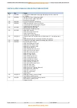
RMT/No/Yes (1-032) 

Delay 

(000–999) 

Outputs ON 

Outputs OFF 

Sounders ON* 

Sounders OFF 

Relays ON 

Relays OFF 

PCB Sounder One ON 

PCB Sounder One 

OFF 

PCB Sounder Two ON 

PCB Sounder Two 

OFF 

Alarm + Flash 

Alert + Flash 

Eme Flash 

Flasher 

Alarm 

Alert 

Emergency 

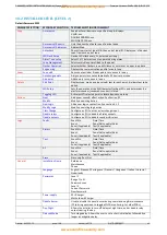
Outputs Marked * have the tone selection option 


ACTIONS (MODIFY) 

For each ACTION (Cause & Effect) previously selected you can: 
Change Input Selection, i.e. Point / Zone / Loop / Panel etc. 
Change Output Selection, i.e. Point / Zone / Loop / Panel etc. 
Erase one or more previous action 
Exit to New / Modify 
  

11- DISABLEMENTS 

11.1 DISABLEMENT 

To aid commissioning and assist routine maintenance checks, various functions of the Quatro fire alarm system can be disabled as 
described below. 

11.2 ZONE DISABLEMENT 

When a zone is disabled, the panel will not respond to any fault or fire signals it receives from DETECTORS from that zone.  

This might be used if the system requires routine maintenance, and the user needs the rest of the system to continue running, but 
doesn’t want spurious false alarms.  

The panel will respond in the usual manner to any events in any non-disabled zones. 

Any number of zones can be disabled, but it is good practice to only disable one zone at a time.  

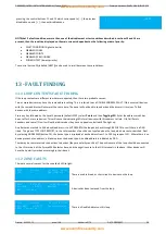
A zone can be disabled as follows:  


Turn the key switch clockwise to the Controls Enabled Position. The controls Active LED will light.  


Press any key followed by the Level 1 password (default 1111). 


 Select 

Zones

 then 

Disable

. Enter the zone(s) or range of zones to be disabled.  


Finally select Accept and then Exit. 

When zones have been disabled, the General Disablement LED will be lit and also the zonal disablement LEDs (in one or both of the 
columns labelled FAULT DISABLE TEST). The zonal disablement LEDs only apply to zones 1 to 20. 

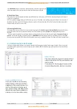
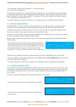
When one or more zones have been disabled, the main screen on the LCD display changes from SYSTEM NORMAL to DISABLED 
ZONES, as shown. 

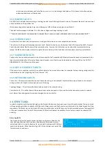
In the example, line 2 indicates that a total of 9 zones have been disabled, and 
the 5th of these is shown on line 3. Zone 1 (Z001) has the text label FIRST FLOOR. 
The zone no. and text label for each disabled zone can be displayed by pressing  

                         18/08/15 09:38 
   DISABLED ZONES             005/009 
   Z001 – FIRST FLOOR 
   [ - ]    [ + ] 

www.acornfiresecurity.com

www.acornfiresecurity.com

Summary of Contents for Premier Quatro QT/1

Page 1: ...INSTALLATION MANUAL Fyreye MKII Firmware Versions PANEL 1 84 LOOP 3 70 MKII PROTOCOL ONE TO FOUR LOOPS ANALOGUE ADDRESSABLE FIRE ALARM PANEL INSTALLATION MANUAL www acornfiresecurity com www acornfir...

Page 2: ...ERNAL LAYOUT 10 3 3 NAVIGATING THE PANEL MENUS 11 3 3 1 NAVIGATING A SET UP SCREEN 11 3 4 CONTROLS 11 3 5 INDICATING DIFFERENT PANEL STATES 12 3 5 1 THE QUIESCENT CONDITION 12 3 5 2 THE ALARM CONDITIO...

Page 3: ...9 REMOTE LED INDICATOR 26 6 4 SETTING THE DEVICE ADDRESS DETECTORS CALL POINTS SOUNDERS AND INTERFACE UNITS 27 6 4 1 SOFT AND HARD PROGRAMMING 27 6 4 2 DIP SWITCH ADDRESS SETTINGS FULL TABLE 27 6 5 FI...

Page 4: ...TALLER LEVEL LEVEL 2 45 10 3 CAUSE EFFECT TABLE 46 11 DISABLEMENTS 47 11 1 DISABLEMENT 47 11 2 ZONE DISABLEMENT 47 11 3 DEVICE DISABLEMENT 48 11 4 SOUNDER DISABLEMENT 48 11 5 RELAY DISABLEMENT 49 11 6...

Page 5: ...and away from damp dirty areas e g in a small cardboard box 1 2 SAFETY PRECAUTIONS DURING NORMAL OPERATION OF PANEL NOTE When the Quatro panel is operating normally i e not being tended by service pe...

Page 6: ...missioned according to our guidelines and the relevant National Standards by an approved and competent person or organization the warranty may become void 2 PANEL SPECIFICATION 2 1 FUNCTIONS REQUIRED...

Page 7: ...itch ON Installer password Configure loops Assign zones Assign Text to each point Modify Alarm Operation Programming Configure network if fitted System Diagnostics LED blink loop Auto check Change pas...

Page 8: ...n 26 V DC MAXIMUM LOOP CURRENT 500 mA NUMBER OF LOOPS 4 MAXIMUM NUMBER OF ZONES 250 Zones MAXIMUM LOOP CAPACITY 250 Addresses MAXIMUM LOOP LENGTH 2 km MAXIMUM LOOP RESISTANCE 44 ohm 22 ohms to 22 ohms...

Page 9: ...c No GLT 215 7 1 Issue 1 36 Author NJ TE DATE 25 05 2017 8 2 5 FUSE SPECIFICATIONS Power Supply Controller PCB Fuse Label Rating Description A_Fuse 2 5A PSU Output Channel A B_Fuse 2 5A PSU Output Cha...

Page 10: ...Fuse Rating Description F1 NOT USED NOT USED F2 F 500 mA 24V Aux Supply Fuse F3 NOT USED NOT USED F4 F 500 mA Conventional Sounder Circuit SND 1 F5 F 500 mA Conventional Sounder Circuit SND 2 F6 F 5 A...

Page 11: ...d with other Quatro panels or repeaters with up to 32 panels per network It has a simple Intuitive Action Programming for configuring sounder relay operations It has an optional add on TCP IP card tha...

Page 12: ...ntered directly with leading zeros if necessary Text fields Use up down cursors to move the cursor in the string 3 4 CONTROLS The panel contains the following mandatory controls They can only be opera...

Page 13: ...ne in fire In the example the first alarm was in Zone 3 Zone 3 is the Second Floor The 2nd line indicates the most recent zone in fire The format is the same as line 1 The most recent fire occurred in...

Page 14: ...the general disablement LEDs are lit steady 10 12 13 13 51 DISABLED ZONES 001 001 Z001 Ground Floor In this example the addressable point at loop 1 address 1 is disabled It is a call point General di...

Page 15: ...etter the description the easier it is to locate in the event of an alarm The panel allows 22 characters It may be necessary to use abbreviations to achieve the required label Keep the design of the s...

Page 16: ...y a battery calculation spreadsheet is available Please contact your distributor for details 4 6 CHOOSING AUDIBLE VISUAL WARNING DEVICES There are a number of options for Audible visual Devices that c...

Page 17: ...ect to the EVACS 16 system It sees each channel of the EVACS as a voice sounder so the panel has control over the individual channels They will be programmed as part of the usual ACTIONS programming f...

Page 18: ...n open circuit reading Also make sure that the screen earth has continuity and is not showing an open circuit Now test between the core making sure there is no short circuit repeat this test between s...

Page 19: ...ng the building It should be fitted to a sturdy wall that will not flex unnecessarily It should ideally be mounted at eye level in order for it to be viewed without need of a ladder It should be insta...

Page 20: ...e Knock out cable entries can be easily removed by Tapping with a suitable screwdriver or chisel from outside the control panel box Take care not to dent or deform the metal enclosure If a grommet is...

Page 21: ...self with the fire alarm panels controls 5 6 CONNECTING THE BATTERIES SOUNDER CIRCUIT DETECTION LOOP MAINS IN EARTH BAR Figure 4 Battery location and connection details To calculate the exact requirem...

Page 22: ...other zone The screen cable at each end of the loop not shown below must be connected to the Panel s earth bar Figure 5 Example of addressable loop wiring top connections to loop cards bottom 6 2 ADDR...

Page 23: ...ng terminals are used for connecting the call point 2 x Negative in terminals note if you only connect to the negative in terminals then the isolator is bypassed 1 x Positive in terminal 1 x Positive...

Page 24: ...llows Terminal L1IN is ve Blue Terminal L2 is ve Brown These are the only two connections required Deep Base MKII CB D Common Base MKII CB 6 3 3 ZAI MI Input Module The end of line resistor value is 2...

Page 25: ...er circuit is 10K When using the ZASC make sure the PSU being used has a fault output relay so that in the event of a power supply fault it is reported to the control panel Note All Power Supplies use...

Page 26: ...l Connecting the sounder is done using the terminals in the back box of the device Please refer to the above diagram 6 3 8 Sandwich Sounder The sandwich sounder has no wiring to connect as it just cli...

Page 27: ...ted version requires a standard detector base Each version of the remote LED can monitor 1 or up to 12 devices The way in which the LED is programmed is either via the DIP switches on the device or so...

Page 28: ...TABLE ADDRESS SWITCHES ADDRESS SWITCHES ADDRESS SWITCHES 1 2 3 4 5 6 7 8 1 2 3 4 5 6 7 8 1 2 3 4 5 6 7 8 0 N O T U S E D 43 OFF OFF ON OFF ON OFF ON ON 86 ON OFF OFF ON OFF ON OFF ON 1 OFF ON ON ON O...

Page 29: ...22 ON OFF ON OFF OFF OFF OFF ON 37 OFF ON OFF ON ON OFF ON ON 80 ON ON ON ON OFF ON OFF ON 123 OFF OFF ON OFF OFF OFF OFF ON 38 ON OFF OFF ON ON OFF ON ON 81 OFF ON ON ON OFF ON OFF ON 124 ON ON OFF O...

Page 30: ...N ON OFF ON ON OFF OFF 244 ON ON OFF ON OFF OFF OFF OFF 159 OFF OFF OFF OFF OFF ON ON OFF 202 ON OFF ON OFF ON ON OFF OFF 245 OFF ON OFF ON OFF OFF OFF OFF 160 ON ON ON ON ON OFF ON OFF 203 OFF OFF ON...

Page 31: ...t low power requirements 450mA max A separate power supply will be required for higher current applications 6 8 FIELD DEVICE TERMINATION S S ER R E Connect loop Earth Screens to Earth Bar Figure 7 Con...

Page 32: ...onfiguration software But to enter it manually at the panel Turn the key switch clockwise to the Controls Enabled Position The controls Active LED will light Press any key followed by the level 2 pass...

Page 33: ...m to always have your loop quality at 100 0 As the quality of communications decreases the chance of the system giving out false alarms or faults increases It can also cause the response from real eve...

Page 34: ...is illustrates the command structure in a menu tree flowchart of the control keys 7 1 13 CONFIGURING THE LOOPS Turn the key switch clockwise to the Controls Enabled Position The controls Active LED wi...

Page 35: ...cted according to its DIP switch setting The installation engineer must now assign a label or location for each device e g ROOM 107 A maximum of 20 characters can be used for each label At the same ti...

Page 36: ...s This is also a good way of tracking down double addresses Turn the key switch clockwise to the Controls Enabled Position The controls Active LED will light Press any key followed by the level 2 pass...

Page 37: ...only one node set as controller on the network Network Filter This determines whether this node reports all network events or just those from a specific network address Node search This should be perf...

Page 38: ...in a master slave topology Multiple slaves can share the same bus but only one master can be in the line at the same time Master can communicate with a specific device peer to peer or with broadcast f...

Page 39: ...FOR MORE INFORMATION ON USING THE MODBUS PLEASE REFER TO THE MODBUS REGISTERS MANUAL Doc No GLT 256 7 2 8 6 REPEATER PANEL The Repeater Panel is used to remotely indicate the status of all CIE s that...

Page 40: ...apply to a detector alarm in Zone 1 and will ignore all other alarms in Zone 1 Multiple point alarm means that at least 2 points devices in Zone 1 must be activated before the programmed Effects occur...

Page 41: ...nd outputs can be selected from 4 categories Point Zone Loop and Panel Example of Selecting a Logic Event New Logic The following example shows LOGIC No 2 top right of LCD being selected The Quatro is...

Page 42: ...e DAY MODE will be active when the day mode is inactive the NIGHT mode will take over Once these settings have been selected press Next to confirm Select the zone range to have the two stage delays ap...

Page 43: ...is same location by pressing Output and changing the delay time as required If a user needs to disable all current delays that are on the panel then this can be done by entering the User menu Delays D...

Page 44: ...it to the required output Same with cause and affects you have the ability to change event type action settings add delays and to also tell the output device whether to active or shut down after a del...

Page 45: ...ELECTION COMMENT Zones Show Displays zone details Show En Zones Indicates enabled zones Show Dis Zones Indicates disabled zones Show Test Zones Displays zones in test mode Enable Enables zones in rang...

Page 46: ...er is fitted Toggling LED Activates LED selected point to locate devices on a loop Actions New Add a new cause effect action See Section 9 1 Modify Modify an existing Action New Logic Add a new logic...

Page 47: ...date to print events from that date to present day Date Time Date xx xx xx Time xx xx Date Time Setup 10 3 CAUSE EFFECT TABLE ACTIONS NEW See also Section 9 1 Input Selection Input Type Selection 1 S...

Page 48: ...user needs the rest of the system to continue running but doesn t want spurious false alarms The panel will respond in the usual manner to any events in any non disabled zones Any number of zones can...

Page 49: ...y changes from SYSTEM NORMAL to DISABLED POINTS as shown In the example line 2 indicates that a total of 5 points have been disabled and the 1st of these is shown on line 3 The 1st disabled device is...

Page 50: ...nd the Alarm sounders will operate for a further 10 seconds If an Alarm occurs on a zone that is not programmed to test the Fire Alarm Panel will continue to operate as normal 12 2 TO PROGRAMME ZONE I...

Page 51: ...more devices This will cause the indicating LEDs for all devices with this address to flash Old Call Points Sounders and some I O units will not be indicated as they have no panel controlled LED to li...

Page 52: ...placing 13 4 SUPPLY FAULTS LOSS OF BATTERY POWER OR LOW BATTERY VOLTAGE Check battery fuse Check that battery connections are secure Check battery voltage should be around 26 27V Check that the two ba...

Page 53: ...T DISABLEMENTS FAULTS section of the panel 13 8 OUT OF SERVICE FAULTS If the system is in a condition in which it is unable to detect a fire or sound the alarm for example if a loop is being configure...

Page 54: ...log see example For a general fault line 2 is simply a description of the fault and there is no information on line 3 The size of the Fault log is 1024 Test Log 512 This category indicates events tha...

Page 55: ...48 Fyreye MKII Addressable Xtratone Sounder MKII AXT 0 65 N A 4 5 64 Fyreye MKII Addressable Xtratone Sounder Beacon MKII AXTB 2 3 N A 20 3 20 Fyreye MKII Addressable Xtratone Flasher MKII AXF 0 6 N A...

Page 56: ...p Quatro panel with 80 Fyreye Extra Addressable Optical Smoke Detectors 15 Zeta Addressable Manual Call Points 20 Zeta Addressable Securetone 2 Sounders and the required standby is 24 hours It will ne...

Page 57: ...Steel QT 3 SS Premier Quatro 4 Loop Analogue Addressable Fire Alarm Panel In Stainless Steel QT 4 SS Premier Quatro 1 Loop Analogue Addressable Fire Alarm Panel In Stainless Steel W Printer QT 1P SS P...

Page 58: ...on 14 2 Mentioned 13 1 should have been 14 1 Added better explanation of selecting test mode with sounders 1 33 14 1 2013 Corrected EOL in sounder connection drawings from 10K to 4k7 1 34 14 8 2015 Re...

Page 59: ...2002 A2 2006 EN54 4 1997 A1 2002 A2 2006 Control and indicating equipment for fire detection and fire alarm systems for buildings Premier Quatro QT 1 QT 2 QT 3 QT 4 Provided options Output to fire ala...

Reviews: