background image

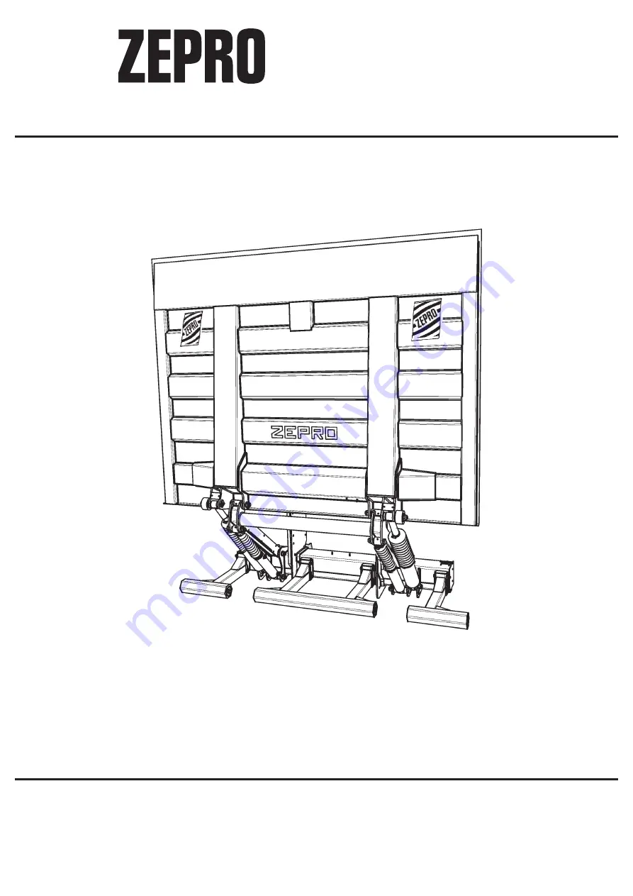
ZHD 3000-150

Sales

Mossvägen 8, 641 49 KATRINEHOLM, SWEDEN

Telephone: 

+46 150 - 489550

Telefax:  

+46 150 - 489551

E-mail:  

[email protected]

Internet: www.zepro.com

Factory

Allévägen 4, 840 73 BISPGÅRDEN, SWEDEN

Telephone: 

+46 696 - 17200

Telefax:  

+46 696 - 17242

E-mail:  

[email protected]

Internet: www.zepro.com

2020-05-14

72689TL

INSTALLATION INSTRUCTION

Z-LYFTEN PRODUKTION AB

Summary of Contents for ZHD 3000-150

Page 1: ...489550 Telefax 46 150 489551 E mail zepro zepro com Internet www zepro com Factory Allévägen 4 840 73 BISPGÅRDEN SWEDEN Telephone 46 696 17200 Telefax 46 696 17242 E mail info zepro com Internet www zepro com 2020 05 14 72689TL INSTALLATION INSTRUCTION Z LYFTEN PRODUKTION AB ...

Page 2: ......

Page 3: ...allation support frame 11 5 Electrical installtion 12 Cable routing of earth and supply cable to the lift 13 Connection of non original components on zepro tail lifts 13 6 Electrical and hydraulic diagram 14 7 Connection unit 19 8 Installation miscellaneous 26 9 Important information 31 10 Markings positioning of decals on lift 32 11 Post installation maintenance 34 12 Testing the lift 35 13 Disma...

Page 4: ...r to certify conformity to the Machinery Directive if the product is subsequently changed without his knowledge or approval In order for the product s CE marking to remain applicable the forms supplied by ZEPRO must be completed in case of modification Welding is not allowed unless specifically recommended by the manufacturer In order to increase security additional decals which are diagrammatic a...

Page 5: ...ff when the lift is not used The lift can also be operated from other optional units To ensure safe operation even with very long control cables the hydraulic unit is equipped with relays The relays situated in the electrical connection box placed in the support frame steer current directly from the main cable to the valves and the main switch for the motor The electric motor is equipped with a th...

Page 6: ...d represent hazards if their weights exceed the equipment s permitted load The following are the ranges of weights for various heavy components Weights Lift components part of cpl lift chassis Support frame ZHD 3000 132 kg Lift arm ZHD 3000 150 63 kg 3 part underrun bar cpl ZHD 3000 150 45 kg Bracket cpl pair ZHD 3000 58 kg Lift cylinder ZHD 3000 150 15 8 kg pce Tilt cylinder ZHD 3000 150 30 6 kg ...

Page 7: ...7 TP2 TP1 40 C C 360 C 530 C 715 TP1 mm 238 229 214 TP2 mm 3000 kg 852 861 876 2 General ZHD 3000 150 steel platform 2000x2580 mm Centre of gravity Max load ...

Page 8: ... A 1 5 mm2 35 mm2 35 mm2 50 mm2 170 Ah 18 Volt 7100 2 General Max Power Consumption Pump Motor Unit Magnet hydraulic unit Magnet electric safety valve Solenoid Cable area Control cable Main cable 8 m Main cable 8 15 m Main cable 15 m Power source Min capacity Min voltage Torque values ...

Page 9: ...9 Loading Diagram 2 General ...

Page 10: ...0 165 877 530 155 915 480 143 947 430 126 975 360 105 1008 max 1500 max 785 244 214 194 C A 40 D ZHD 3000 150 1524 min 750 max 930 1524 1970 2418 1443 994 245 245 A max 1037 max 550 34 35 62 100 385 350 617 817 133 301 3 Dimensions for installation ...

Page 11: ...er to let oil or air out The brackets should be positioned according to picture 4 Slide the brackets over the support frame so that the opening points towards the front of the vehicle see picture 4 If adjustment is necessary drill 16 5 mm holes in the truck frame in the middle of the oval holes of the bracket Then fasten the brackets securely to the frame torque 180 Nm with the delivered M16x60 8 ...

Page 12: ...ding and the risk of fire If you have a spiral cable unit its cable colours are different see electric diagram Check that the hydraulic unit is well earthed according to truck manufacturer s instructions earthing is made through leading in plate se picture If you must lead a spiral cable up through the floor you must protect it with a sheath up from the floor If you need to use power from the circ...

Page 13: ...is done with similar care to avoid damage from contact with edges of the frame and other parts of the vehicle This will increase the life of the cables and reduce the risk of unnecessary downtime Connection of non original components on zepro tail lifts It has always been forbidden to connect foreign equipment both electric and hydraulic on all Zepro tail lifts Using non original components can af...

Page 14: ...k nr Ritningsnr Drawing nr Blad Sheet Format Size Revision För denna ritning gäller IS0 toleranser SMS ritregler Toleranser Tolerance Ytjämnhet Surface finish Svets Welding 1 1 Ritad Drawn A HIAB brand part of Cargotec Corporation Samm Used on Rev Rev Tag Datum Date Ändring Rev number Införd av Revised by Kontrol Checked Godk Approved A 2011 04 16 6417 MB MB CL B 2012 11 12 6698 ME MB CL C 2013 03...

Page 15: ...te Rev number Revised ECR Approved A 2012 11 12 6698 ME MB CL B 2013 03 04 6763 TH MB CL C 2013 04 10 6791 TH 52 CL D 2014 04 04 6954 TH 176 CL E 2014 06 25 7025 TH 207 TH F 2016 02 22 7227 MB PS G 2017 08 08 7435 ME 735 PS Ctrl 4 Spiral Ctrl 3 Radio Ctrl 2 Ctrl 1 Control Power Sensor Power Ground IN OUT Ai 1 Ai 2 Di 1 Di 2 Di 3 Di 4 Di 5 Di 6 PA PA CSPWR CS B E C 2H1 B E C 2H2 B E C Lock B E C Lo...

Page 16: ...switch Alarm for open platform 6 Electric and hydraulic diagram Cs Pa Sensor Power Di4 Cabin switch Alarm for open platform when control unit has main switch Control Power Ps1 Tiltcylinder Pump Unit Cs Pa Gnd Cs ...

Page 17: ...a tion clearly visible so that the driver can see it in the mirror The light must be of amber color Connect the lamp indicator according to the electric diagram 3A fuse connected between the circuit card and the pressure switch Alarm for open platform trailer 6 Electric and hydraulic diagram Gnd Sensor Power ...

Page 18: ...aulic diagram 3 button remote control unit with spiral cable 3 button control unit Nr No Färg Color Farbe 1 Gul Grön Yellow Green Gelb Grün 2 Blå Blue Blau 3 Brun Brown Braun 4 Svart Black Schwarz 5 Grön Green Grün 6 Vit White Weiß 7 Röd Red Rot 8 Gul Yellow Gelb 9 Grå Grey Grau 10 Orange Orange Orange ...

Page 19: ...lt display Program configuration The flashing light indicates Supply voltage Off No supply voltage On Supply voltage available but CS cabin switch is not active Flashing CS cabin switch is active the system is awaiting input signal LED 1 indicates Active input button s on control device pressed LED 2 indicates Active output lift in operation Ctrl 4 Spiral Ctrl 3 Radio Ctrl 2 Ctrl 1 Control Power S...

Page 20: ...sed by the figures 1 7 1 Fixed control device 1 including two hand button 2h1 2 Fixed control device 2 including two hand button 2h2 3 Radio control device External 4 Coil control device 5 Truck slider control device 6 Radio control device internal module 7 CS cabin switch Once a button has been released the control system for the current control device is locked for a while to ensure that no othe...

Page 21: ...d for This primarily applies to radio and coil con trol devices as other control devices have such a short locking period that there is no time to see the indication The number will stop flashing when one of the current control device s buttons are pressed If the control card has been without voltage and receives the voltage again when the CS cabin switch is switched on 7 will flash on the display...

Page 22: ...gh a list containing the five latest faults detected before the display goes off Fault codes Identification Code 1 Code 2 Code 3 Information Other L Low battery voltage 07 35 Voltage measured H High battery voltage 07 35 Voltage measured E Control device locked 1 Fixed control device incl two hand button 2h1 if they are monitored 2 Fixed control device 2 incl two hand button 2h2 if they are monito...

Page 23: ...t codes Output No 3 short circuited Supply voltage A supply voltage of between 8 0V and 15 0V is regarded by the unit as correct for a 12V system A supply voltage of between 18 0V and 29 0V is regarded by the unit as correct for a 24V system All functions on the unit cease when the supply voltage is less than 7 0V If the supply voltage then rises to more than 7 0V functionality is restored Control...

Page 24: ...ch opens oil return directly to tank Indicates lift arm at ground Prevents unwanted down tilting with hydraulic auto tilt Pressure guard for dropping pressure connected to the tilt cylinders side sends when in neutral mode connected signal back to Di4 which in turn sends a signal out on Pa or provides Di4 with signal from a tilt sensor in the foot control unit cable set to indicate platform open P...

Page 25: ...ANKLÅDA CHASSIS WITH TANK ÖLTANK TANKLOCK FILLER CAP TANKDECKEL VENTILHUS VALVE BODY VENTIL GEHAUSE MOTOR SOLENOID SWITCH MAGNETSCHELTER S U1 U3 U2 KRETSKORT CIRCUIT CARD GETRUCTE SCHALTUNG KOPPLINGSENHET CONNECTION UNIT KOPPLUNGS EINHEIT ...

Page 26: ...kets can be adjusted to 4 different height positions pict 6 The outer brackets can be adjusted to 5 different horizontal positions pict 6 1 The lateral distance between bumper bar and moving parts of the tail lift must not exceed 25 mm The bumper bar must in each case have an effective surface area of at least 350cm2 pict 7 The bumper bar can be positioned further back and lower than the given dim...

Page 27: ...he values below which are particulary relevant when installing a rubber seal on the body at the top of the platform Steel Pict 12 Pict 11 Pict 10 Type Installation of platform Install platform onto the lift arms and tilt cylinders to the platform Use axles and support wheels provided Axles is locked with eye bolt incl screw M12x25 80Nm bag 380 and 381 NOTE O rings must be installed at the same tim...

Page 28: ...lt is installed 1 pce angle sensor should be installed as in pict 15 1 Sealing system vertical Install the rails for the vertical sealing strips Note the position of the lock ears They can be fastened with screws rivets or welding The rubber strips are installed after the lock ears The rubber strips are locked by pressing the rails together If upper seal must be installed you must mitre 45 degrees...

Page 29: ...lock screws see pict 17 6 Turn the adjustment collar as per pict 17 so that the platform fits exactly to the body as per pict 16A 7 Assemble the other cylinder in the platform 8 Loosen 3 pcs lock screws see pict 17 9 Turn the adjustment collar as per pict 17 so that the platform fits exactly to the body as per pict 16A 10 Then adjust both cylinders the last bit alternately so that the platform fit...

Page 30: ...oor level see pict 22 2 Loosen the ring s lock screw 2 Screw the ring out in the direction of the platform 3 See pict 23 3 Tilt down the platform to maximum 10 degrees under horizontal As per pict 22 4 Adjust the ring to the top of the cylinder 4 5 Tighten the lock screw in the ring 5 See pict 24 Reassemble rubber bellows see pict 21 Lock screws torque is between 3 5 Nm Note Both cylinders tilt do...

Page 31: ...hen the final post installation testing is carried out it is important that there is sufficient clearance between the cylinders working envelopes and all fixed points During lift operation and cylinder mo vement there is a risk for conflict with the subframe truck frame number plate lamp holders and even the mounting brackets when the overhang is very limited due to lift arm angle Hence it is impo...

Page 32: ... nominal loading and the diagram shows the maximum permitted loading at different positions on the platform The name plate is installed on the support frame of the tail lift and contains the following information Lift type Maximum permitted load in kg Serial number Year of manufacture Address and tel no of the manufacturer Country of manufacture Type no for bumper bar certificate RUPD Type no for ...

Page 33: ...33 10 Markings decals ...

Page 34: ...lower bearing 2 Left liftcylinder lower bearing 3 Right liftcylinder upper bearing 4 Left liftcylinder upper bearing The hydraulic unit tank is filled with a mineral based hydraulic oil art no 21963 for 1 litre or a biodegradable synthetic oil art no 22235 for 1 litre There is a sticker on the hydraulic unit indicating which type of oil is in the tank ...

Page 35: ... and loading capacity Remove the load from the platform Repeat the measurements of A B C D and check that there is no permanent deformation to the tail lift or its brackets Deflection Place a test load on the platform according to the table for the corresponding tail lift model and loading capacity The tail lift should be in the same level and angle as floor Leave the test load on the platform for...

Page 36: ...hat the tail lift will not operate if the cabin switch is in the off position That the tail lift cannot be operated when the main current fuse is removed where applicable That the overflow valve is activated when the lift is run up to the floor level or armstops That the tail lift cannot be lowered or tilted down respectively if the electrical connector from the lift and tilt cylinders respectivel...

Page 37: ...ylinders on the ground 4 Run the tilt cylinders to their minimum stroke limit to remove pressure from the circuit 5 Dismantle the tilt cylinder s lower axle at the support frame Remove the cylinder and take away the hoses NB Oil can leak from the hoses and cylinder 6 Dismantle the platform s axles Lift away the platform lower the liftarm to the ground 7 Unscrew the lift cylinder s upper axle at th...

Reviews: