background image

MAIN MOVING SYSTEM

EM -55

REASSEMBLY

ECCF87EF

1.

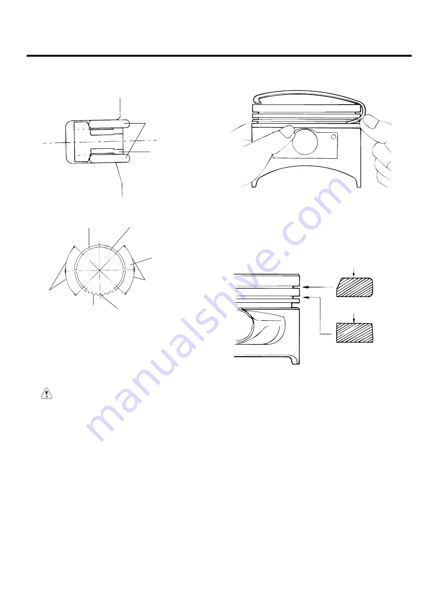
Install the spacer.

Piston upper

Piston lower

Side rail

Spacer

ECA9082A

Upper side rail

45˚

45˚

45˚

45˚

Lower side rail

90˚ Position 
from the gap 
of No. 2 ring

Gap position of 
lower side rail

Gap position of spacer

Gap position 
of upper 
spacer

Spacer

EDJA490A

2.

Install the upper side rail. To install the side rail, first
put one end of the side rail between the piston ring
groove and spacer, hold it firmly, and press down with
a finger on the portion to be inserted into the groove
(as illustrated).

CAUTION

Do not use a piston ring expander when installing
side rail.

3.

Install the lower side rail by the same procedure de-
scribed in Step 2.

ECA9380B

4.

Apply engine oil around the piston and piston grooves.

5.

Using a piston ring expander, install the No.2 piston
ring.

6.

Install the No. 1 piston ring.

No.1

No.2

Berrel type

Inside bevel

Taper type

EDDA037B

7.

Position each piston ring end gap as far away from
its neighboring gaps as possible. Make sure that the
gaps are not positioned in the thrust and pin direc-
tions.

ZENITH POWER PRODUCTS - 416

Summary of Contents for ZPP 416

Page 1: ......

Page 2: ...CYLINDER HEAD MAIN MOVING SYSTEM CAM SHAFT CRANK SHAFT FLY WHEEL PISTON COOLING SYSTEM ENGINE COOLANT HOSE PIPES ENGINE COOLANT PUMP RADIATOR RADIATOR CAP THERMOSTAT LUBRICATION SYSTEM OIL PUMP ENGINE BLOCK ENGINE BLOCK INTAKE AND EXHAUST SYSTEM EXHAUST MANIFOLD INTAKE MANIFOLD ...

Page 3: ...m 0 012 in O S 0 6mm 0 024 in O S Exhaust 0 3mm 0 012 in O S 0 6mm 0 024 in O S Max 0 03mm 0 0012 in 0 15mm 0 0059 in 30 7 30 721 mm 1 2087 1 2095 in 31 0 31 021 mm 1 2205 1 2213 in 27 3 27 321mm 1 0748 1 0756 in 27 6 27 621mm 1 0866 1 0874 in 0 1 mm 0 0039in 0 2mm 0 008in Oversize rework dimensions of valve Guide hole 0 05mm 0 002 in O S 0 25mm 0 010 in O S 0 50mm 0 020 in O S 11 05 11 068mm 0 43...

Page 4: ...e Oversize 0 8 1 2mm 0 031 0 047 in 1 3 1 7mm 0 051 0 066 in 45 0 3 0 6mm 0 012 0 024 in oversize Valve spring Free length Load Squareness 44 00mm 1 7323 in 21 6kg 35mm 47 6lb 1 3780 in 45 1kg 27 2mm 99 4lb 1 071 in 1 5 or less Cylinder block Cylinder bore Out of round and taper of cylinder bore Clearance with piston 76 50 76 53mm 3 0118 3 0130 in Less than 0 01mm 0 0004 in 0 025 0 045mm 0 0009 0 ...

Page 5: ...20 in 0 75mm 0 030 in 49 727 49 742mm 1 9577 1 9583 in 49 477 49 492mm 1 9479 1 9485 in 49 227 49 242mm 1 9380 1 9386 in Flywheel Runout 0 1mm 0 0039 in 0 13mm 0 0051in Oil pump Clearance between outer circumference and front case body clearance Front case tip clearance Side clearance Inner gear Outer gear 0 12 0 18mm 0 0047 0 0070 in 0 025 0 069mm 0 001 0 0027 in 0 04 0 085mm 0 0016 0 0033 in 0 0...

Page 6: ...ne coolant temperature sensor Type Resistance Heat sensitive thermistor type 2 31 2 59k at 20 C 68 F 146 9 147 3 at 110 C 230 F Air cleaner Type Element Dry type Un woven cloth type Exhaust pipe Muffler Suspension system Expansion resonance type Rubber hangers NOTE O D Outer Diameter I D Inner Diameter O S Oversize Diameter U S Undersize Diameter ZENITH POWER PRODUCTS 416 ...

Page 7: ...1 44 89 96 89 96 Timing system Crankshaft pulley bolt Camshaft sprocket bolt Timing belt tensioner bolt Timing belt idle bolt Timing belt cover bolt Front case bolt 140 150 80 100 20 27 43 55 8 10 20 27 1400 1500 800 1000 200 270 430 550 80 100 200 270 103 111 59 74 15 20 32 41 6 7 15 20 Engine Mounting Right mounting insulator large bolt Right mounting insulator small nut Transmission mount insul...

Page 8: ...nd bolts Surge tank stay to cylinder block bolts Throttle body to surge tank bolts Exhaust manifold to cylinder head nuts Exhaust manifold cover to exhaust manifold bolts Oxygen sensor to exhaust manifold Front exhaust pipe to exhaust manifold nuts Front exhaust pipe bracket bolts Front exhaust pipe to catalytic converter bolts 8 10 4 6 15 20 18 25 15 20 25 30 15 20 50 60 30 40 30 40 40 60 80 100 ...

Page 9: ...with coolant or gasoline and that it has the proper viscos ity CHANGING ENGINE OIL CAUTION Be careful not to burn yourself as the engine oil is hot 1 Run the engine until it reaches normal operating tem perature 2 Turn off the engine 3 Remove the oil filler cap and the drain plug on the oil pan Drain the engine oil KCPC001B 4 Install and tighten the drain plug to the specified torque Tightening to...

Page 10: ...fore installing the new filter Part number EDDA063A PROCEDURE FOR REPLACING THE OIL FILTER CAUTION Be careful not to burn yourself as the engine and engine oil are hot 1 Use a filter wrench to remove the oil filter 2 Before installing the new oil filter on the engine apply clean engine oil to the surface of the rubber gasket Apply engine oil to the surface EDDA063B 3 Tighten the oil filter to the ...

Page 11: ... operation 20 10 10 15 25 13 5 14 50 68 C 40 F 104 15W 50 40 10W 50 40 20W 50 40 10W 30 5W 20 5W 30 1 2 1 5W 40 1 EDA9990B NOTE For best performance and maximum protection of all types of operation select only those lubricants which 1 Satisfy the requirements of the API classification 2 Have proper SAE grade number for expected am bient temperature range Lubricant that does not have both an SAE gr...

Page 12: ... is removed be careful not to spill any coolant from it 4 Be careful when installing and removing the tester and when testing not to deform the filler neck of the radiator 4 If there is leakage repair or replace with the apropri ate part KDPC001F RADIATOR CAP PRESSURE TEST 1 Remove the radiator cap wet its seal with engine coolant then install it on the tester 2 Increase the pressure until the gau...

Page 13: ...74 1 069 1 064 1 058 30 22 25 13 45 1 087 1 082 1 076 1 070 1 064 36 32 8 31 23 8 50 1 095 1 090 1 084 1 077 1 070 42 44 37 35 55 1 103 1 098 1 092 1 084 1 076 50 58 45 49 60 Example The safe operating temperature is 15 C 5 F when the measured specific gravity is 1 058 at coolant temperature of 20 C 68 F CAUTION If the concentration of the coolant is below 30 its anti corrosion properties will be ...

Page 14: ...n until it warms up the radiator fan comes on at least twice 8 Turn off the engine Check the level in the radiator add coolant if needed 9 Put the radiator cap on tightly then run the engine again and check for leaks CHECKING COMPRESSION PRESSURE 1 Before checking engine compression check the en gine oil level Also check that the starter motor and battery are all in normal operating condition 2 Ch...

Page 15: ...akes the compression to rise it is likely that there may be wear between the piston ring and cylinder wall 2 If compression remains the same valve seizure poor valve seating or a compression leak from the cylinder head gasket are all possible causes Tightening torque Spark plug 20 30 Nm 200 300 kg cm 14 22 lb ft ADJUSTING TIMING BELT TENSION 1 Rotate the steering wheel counter clockwise throughly ...

Page 16: ...nd belt coincide with each other 12 Tighten the slot side bolt first and then tighten the bolt of pivot side 13 Check the tension of the timing belt When the tensioner and the tension side of the timing belt are pushed in horizontally with a moderate force approx 49N 11 lb the the timing belt log end is ap prox half of the tensioner mounting bolt head radius cross flats away from the bolt head cen...

Page 17: ...d check the belt for wear damage or breakage on the pul ley contact surface and check the pulley for scoring Also check the amount that the belt is deflected Pulley V ribbed belt Wrong Wrong Right ECA9980A STANDARD VALUE Adjustment Itmes Inspection New Used Deflection mm in 5 1 6 0 0 200 0 236 4 0 4 4 0 157 0 173 5 0 5 7 0 200 0 224 For alternator Tension N lb 350 500 79 112 650 750 143 165 400 50...

Page 18: ...TENSION GAUGE 1 When measuring turn the reset button in the direction of the arrow and set the gauge needle to the RESET position 2 If the tension gauge is removed from the belt the nee dle will still indicate the tension Read the tension value after removing the gauge Typ B Spindle V ribbed belt Hook RESET button RESET position ECA9980D ADJUSTING THE ALTERNATOR BELT CAUTION If the belt is too loo...

Page 19: ...l seal Crankshaft front oil seal guide 09231 22100 ECKA010D Guide of oil seal Camshaft oil seal installer 09221 21000 EDDA005B Installation of the camshaft oil seal Valve guide installer 09221 3F100 A B ECKA010B Removal and installation of valve guides Valve stem oil seal installer 09222 22001 ECKA010A Installation of valve stem oil seals ZENITH POWER PRODUCTS 416 ...

Page 20: ...00 EDDA005C Removal and installation of intake and exhaust valves Water temperature sensor socket wrench 09221 25100 EDKD101B Removal and installation of the water temperature sensor Crankshaft rear oil seal installer 09231 21000 EDDA005F Installation of engine real oil seal and crankshaft rear oil seal ZENITH POWER PRODUCTS 416 ...

Page 21: ... bracket Re tighten Loose center member Re tighten Broken transaxle mount insulator Replace Broken engine mount insulator Replace Excessive engine vibration Broken engine roll stopper insulator Replace Thin or diluted engine oil low oil pressure Change Worn or damaged valve stem or valve guide Replace Noisy valves HLA abnormal operation Speed the engine up for venting or Replace the HLA Insufficie...

Page 22: ...t Refill coolant Faulty thermostat Replace Abnormally low coolant temperature Faulty temperature sensor wiring Repair or replace Inoperative electrical cooling fan Damaged thermo sensor electrical motor radiator fan relay and wiring fuse Replace or repair Loose connections Retighten Exhaust gas leakage Broken pipe or muffler Repair or replace Detached baffle plate in muffler Replace Broken rubber ...

Page 23: ...Timing belt Idler 43 55 430 550 32 40 Crankshaft sprocket Ten sioner 20 27 200 270 15 20 Timing belt lower cover Crankshaft pulley 140 150 1400 1500 103 111 Flange Timing belt upper cover 80 100 800 1000 59 74 Camshaft sprocket TORQUE Nm kgf cm lbf ft EDKD100A ZENITH POWER PRODUCTS 416 ...

Page 24: ...CDA125K 2 Remove the engine support bracket 14 mm bolt and 2 nuts 17 mm bolt KDDC003B 3 Remove the power steering belt 4 Remove the air conditioning compressor belt 5 Remove the alternator belt KBPD160A KBPD160B 6 Remove the coolant pump pulley KDDC004B ZENITH POWER PRODUCTS 416 ...

Page 25: ...he timing belt NOTE If the timing belt is reused mark with an arrow to in dicate direction of rotation on the front of the engine to make sure that the belt is reinstalled in the same direction as before ECDA121B 11 Remove the camshaft from the camshaft sprocket 12 Remove the crankshaft sprocket and flange 13 Remove the timing belt idler 14 Remove the timing belt tensioner KDPC008C ZENITH POWER PR...

Page 26: ... rotation and check for play or noise Replace as necessary 3 Replace the pulley if there is a grease leak from its bearing EDKD106A TIMING BELT 1 Check the belt for oil or dust deposits Replace if necessary Small deposits should be wiped away with a dry cloth or paper Do not clean with solvent 2 When the engine is overhauled or belt tension ad justed check the belt carefully If any of the followin...

Page 27: ...A093E Separation EDDA093F 3 Cracked or separating canvas Crack Separation EDDA093G 4 Badly worn teeth initial stages Canvas on load side of tooth flank worn Fluffy canvas fibers rubber gone and color changed to white and unclear canvas texture Flank worn On load side EDDA093H 5 Badly worn teeth last stage Canvas on load side of tooth flank worn down and rubber exposed tooth width reduced Rubber ex...

Page 28: ... Cracked tooth bottom Crack EDDA093J 7 Missing tooth Tooth missing and canvas fiber exposed EDDA093K 8 Side of belt badly worn NOTE Normal belt shluld have precisely cut sides as if cut by a sharp knife 9 Side of belt cracked ZENITH POWER PRODUCTS 416 ...

Page 29: ... torque Idler bolt 43 55 Nm 430 550 kg cm 32 41 lb ft EDKE103A 4 Align the timing marks of the camshaft sprocket A and camshaft bearing cap B Then align the timing marks of crankshaft sprocket and front case with the No 1 piston placed at top dead center on its compression stroke as shown in the illus tration A B ECDD008F EDKE107A 5 To install the timing belt tensioner first mount the ten sioner s...

Page 30: ...0 27 Nm 200 270 kg cm 15 20 lb ft 10 Turn the crankshaft two turns in its operating direction clock wise and realign the camshaft sprocket timing mark with the top dead center position 11 Then recheck the belt tension Verify that when the tensioner and the tension side of the timing belt are pushed in horizontally with a moderate force approx 49N 11lb the timing belt cog end is aprox 1 2 of the te...

Page 31: ...mp pulley KDDC004B 15 Install the alternator belt and adjust the belt tension 16 Install the air conditioning compressor belt and adjust the belt tension 17 Install the power steering belt and adjust the belt ten sion ZENITH POWER PRODUCTS 416 ...

Page 32: ...Y CYLINDER HEAD COMPONENTS E804EE47 Cylinder head cover Gasket Cylinder head bolt 30 300 22 90 Release all bolts 30 300 22 90 8 10 80 100 6 7 4 Cylinder head Cylinder head gasket Cylinder block TORQUE Nm kgf cm lbf ft EDKD110A ZENITH POWER PRODUCTS 416 ...

Page 33: ...Retainer lock Valve spring Spring seat Valve Stem seal Timing chain Chain sprocket Exhaust camshaft Camshaft sprocket 80 100 800 100 59 74 12 14 120 140 9 10 Intake camshaft TORQUE Nm kgf cm lbf ft EDKD111A ZENITH POWER PRODUCTS 416 ...

Page 34: ...valve stem seals EDDE088B INSPECTION EE4FDB50 CYLINDER HEAD 1 Check the cylinder head for cracks damage and coolant leakage If cracked replace the cylinder head 2 Remove scale sealing compound and carbon deop sits completely After cleaning the oil passages ap ply compressed air to verify that the passages are not clogged ECKD001H 3 Check the cylinder head surface for flatness in the di rection as ...

Page 35: ...each valve spring If they exceed the servicd limit replace the springs 2 Using a square test the squareness of each spring If a spring is excessively out of square replace it Valve spring Standard Free height 44 mm 1 7323 in Load 21 6 kg 35 mm 47 6 lb 1 3780 in 45 1 kg 27 2 mm 99 4 lb 1 0709 in Out of square 1 5 Limit Free height 1 0 mm 0 039 in Out of square 3 2 Free height Out of square ECA9281C...

Page 36: ...70 in VALVE SEAT INSERT OVERSIZES Description Size mm in Size mark Seat ring height H mm in Oversize hole diameter I D mm in 0 3 0 012 O S 30 5 1 5 3 0 2008 0 2087 30 7 30 721 1 2087 1 2095 Intake valve Seat ring 0 6 0 024 O S 60 5 4 5 6 0 2126 0 2205 31 0 31 021 1 2205 1 2213 0 3 0 012 O S 30 6 2 6 4 0 2441 0 2520 27 3 27 321 1 0748 1 0756 Exhaust valve Seat ring 0 6 0 024 O S 60 6 5 6 7 0 2560 0...

Page 37: ... insert a new valve and check for proper the clearance 5 After the valve guide is replaced check that the valve is seated properly Recondition the valve seats as necessary VALVE GUIDE OVERSIZES Over size mm in Size mark Oversize valve guide hole size mm in 0 05 0 002 5 11 05 11 068 0 4350 0 4357 0 25 0 010 25 11 25 11 268 0 4429 0 4436 0 50 0 020 50 11 50 11 518 0 4528 0 4535 ZENITH POWER PRODUCTS...

Page 38: ...retainer Enamel coated side Spring Spring Retainer Stem seal Spring seat ECA9290B 4 Using the special tool 09222 28000 09222 28100 compress the spring and install the retainer locks Af ter installing the valves ensure that the retainer locks are correctly in place before releasing the valve spring compressor 09222 28100 09222 28000 EDKD116A NOTE When the spring is compressed Check that the valve s...

Page 39: ...E8F4E76 TORQUE Nm kg cm lb ft 5 8 50 80 4 6 8 10 80 100 6 7 12 14 50 80 4 6 Bearing cap rear Exhaust camshaft HLA 80 100 800 1000 59 74 Camshaft oil seal Bearing cap front Intake camshaft Cylinder head Gasket Camshaft sprocket EDDA018A ZENITH POWER PRODUCTS 416 ...

Page 40: ...remove the center cover 3 Remove the ignition coil assembly and the spark plug cables KCDC002B 4 Loosen the cylinder head cover bolts and then remove the cylinder head cover EDKE104A 5 Remove the camshaft sprocket 6 Remove the camshaft bearing caps and timing chain EDKE124A 7 Remove the camshaft 8 Remove the HLA ZENITH POWER PRODUCTS 416 ...

Page 41: ...84 mm 1 6909 in Exhaust 43 3489 mm 1 7066 in ECKD223A 3 Check the cam surface for abnormal wear or damage and replace if necessary 4 Check each bearing for damage If the bearing surface is excessively damaged replace the cylinder head assembly or camshaft bearing cap as neces sary Camshaft end play 0 1 0 2 mm 0 0039 0 0079 in OIL SEAL 1 Check the lips for wear If the lip threads are worn replace 2...

Page 42: ...engine runs at 2000 3000 rpm If it doesn t disappear refer to item 7 below Continuous noise when engine is running after changing HLA Oil drain out of the high pressure chamber in HLA allowing air to get in Insufficient oil in HLA CAUTION Do not run engine at a speed higher than 3000 rpm as this may damage HLA Engine oil level too high or too low Check oil level Drain or add oil as necessary Exces...

Page 43: ...ark Timing mark Timing chain EDDA021A 3 Install the camshaft after lubricating the camshaft journals with engine oil EDDA021B 4 Install the bearing caps The markings on the caps are for intake exhaust identification I Intake camshaft E Exhaust camshaft Symbol identifying intake Cap number EDDA021C 5 Tighten the bearing caps to the specified torque in two or three steps as shown Tightening torque B...

Page 44: ...t 80 100Nm 800 1000 kg cm 59 74 lb ft EDKE105A 8 Align the camshaft sprocket and crankshaft sprocket timing marks Place the poston in the No 1 cylinder to top dead center on the compression strokie Refer to the timing belt 9 Install the cylinder head cover Tightening torque Cylinder head cover bolts 8 10 Nm 80 100 kg cm 6 7 lb ft EDKE104A 10 Install the spark plug cables ignition coil assembly and...

Page 45: ... 8 8 Rear oil seal case Gasket Cylinder block Center bearing Crankshaft Main bearing Main bearing cap 55 60 550 600 41 44 10 12 100 120 7 3 8 8 Oil pan Drain plug 40 45 400 450 30 33 Gasket 15 22 150 220 11 16 Oil screen Gasket Front case Oil seal 20 27 200 270 14 7 20 TORQUE Nm kgf cm lbf ft EDKD140A ZENITH POWER PRODUCTS 416 ...

Page 46: ...Measure the diameter of the crankshaft journal and pin 2 Measure the diameter of the crankshaft bore and con necting rod bore 3 Measure the thickness of the crankshaft bearing and connecting rod bearing 4 Measure the clearance by the value that subtract the diameter of journal and pin and the thickness of bear ing from the diameter of bore Connecting rod bearing oil clearance 0 018 0 036 mm 0 0007...

Page 47: ...ze code shown first Main journal size code ECPC004B CRANKSHAFT MAIN JOURNAL DIAMETER Class Main journal diameter Size code I 49 968 49 962 mm 1 9672 1 9670 in Λ II 49 962 49 956 mm 1 9670 1 9667 in b III 49 956 49 950 mm 1 9667 1 9665 in c MAIN JOURNAL BEARING THICKNESS No 1 2 4 5 MAIN BEARING Color Main journal bearing thinckness Yellow 2 002 2 005 mm 0 0788 0 0789 in Green 2 005 2 008 mm 0 0789 ...

Page 48: ...t be correct Tightening torque Main bearing cap bolt 55 60 Nm 550 600 kg cm 41 44 lb ft Connecting rod cap bolt 32 35 Nm 320 350 kg cm 24 26 lb ft EDKE151A 4 Make certain that the crankshaft turns freely and has the proper clearance between the center main bear ing thrust flange and the connecting rod big end bear ing Standard value Crankshaft end play 0 05 0 175 mm 0 0019 0 0068 in ECKD001B 5 Ins...

Page 49: ...el INSPECTION EB2E8F43 1 Check the clutch disc contacting surface of the fly wheel for damage and wear Replace the flywheel if excessively damaged or worn 2 Check the clutch disc contacting surface of the fly wheel for runout Standard value Flywheel run out 0 1 mm 0 0039 in 3 Check the ring gear for damage cracks and wear and replace if necessary REASSEMBLY E650BE51 Install the flywheel assembly a...

Page 50: ...SYSTEM EM 49 PISTON COMPONENTS E1D1ECDE Piston ring Piston Connecting rod Piston pin Connecting rod bearing Connecting rod bearing cap 32 35 320 350 24 26 TORQUE Nm kgf cm lbf ft EDKD141A ZENITH POWER PRODUCTS 416 ...

Page 51: ...od is supported by fork inserts 4 To remove the pin from the piston place the piston in the support fixture with the rod resting on the fork inserts Pass the remove tool through the top of the support fixture and use it to press out the pin Remover Support fixture Support fork EDA9048A 5 To install a new pin the proper fork inserts must be in place to support the rod 6 Position the rod inside the ...

Page 52: ...od little end Continue pressing until the pin guide falls free and the installer tool seats against the top of the arch CAUTION Do not exceed 1250 500 kg 2765 1102 lb of force when the installing tool seats against the top of the arch Press Installer Support fix Adapter Piston pin Piston Connecting rod Universal fork insert Pin guide HEW20A55 ZENITH POWER PRODUCTS 416 ...

Page 53: ... replace the piston and rings together If it is less than the service limit replace the piston rings only Piston ring side clearance No 1 0 04 0 085 mm 0 0016 0 0033 in No 2 0 04 0 085 mm 0 0016 0 0033 in Limit No 1 0 1 mm 0 004 in No 2 0 1 mm 0 004 in ECKD001G 2 To measure the piston ring end gap insert a piston ring into the cylinder bore Position the ring at right angles in the cylinder wall by...

Page 54: ...sure that the cylinder numbers marked on rod end cap at disassembly match When a new connecting rod is installed make sure that the notches holding the bearing in place are on the same side 2 Replace the connecting rod if it is damaged at either end of the thrust faces If it has a stratified wear in or if the surface of the inside diameter of the small end is severely rough replace the rod Notches...

Page 55: ...121 3 0126in B C 76 52 76 53mm 3 0126 3 0129in C 2 Check the piston size code on the piston top face KDPC005Z NOTE Stamp the grade mark of basic diameter with rubber stamp 1 6 L Class Piston outer diameter Size code A 76 465 76 475mm 3 0104 3 0108in A B 76 475 76 485mm 3 0108 3 0112in B C 76 485 76 495mm 3 0112 3 0116in C 3 Select the piston related to cylinder bore class Oil clearance 0 025 0 045...

Page 56: ... it firmly and press down with a finger on the portion to be inserted into the groove as illustrated CAUTION Do not use a piston ring expander when installing side rail 3 Install the lower side rail by the same procedure de scribed in Step 2 ECA9380B 4 Apply engine oil around the piston and piston grooves 5 Using a piston ring expander install the No 2 piston ring 6 Install the No 1 piston ring No...

Page 57: ...od is installed make sure that the notches for holding the bearing in place are on the same side 13 When assembling bolts should be fastened by the angle torque controlled method as the following 1 Apply oil to the thread of nuts and spot areas 2 Tighten the connecting rod bolt Tightening torque Connecting rod cap nut 32 35 Nm 320 350 kg cm 24 26 lb ft CAUTION After removing the connecting rod bol...

Page 58: ...COOLING SYSTEM EM 57 COOLING SYSTEM ENGINE COOLANT HOSE PIPES COMPONENTS E2BAF9FA RADIATOR CYL HEAD CYL BLCOK BYPASS VALVE HEATER THERMOSTAT COOLANT PUMP ECKB001I ZENITH POWER PRODUCTS 416 ...

Page 59: ...stat housing Thermostat 15 20 150 200 9 14 Coolant inlet fitting Gasket 10 15 100 150 7 9 Coolant inlet pipe O ring Water pump 12 15 120 150 8 8 11 20 27 200 270 12 20 TORQUE Nm kgf cm lbf ft EDKD180A ZENITH POWER PRODUCTS 416 ...

Page 60: ...ant inlet pipe end wet the O ring with coolant and insert the coolant inlet pipe NOTE 1 Do not apply oil or grease to the coolant pipe O ring 2 Keep the coolant pipe connections free of sand dust etc 3 Insert the coolant pipe fully into the cylinder block 4 Do not reuse the O ring Replace it with a new part Cylinder block Coolant inlet pipe Coolant pump assembly ECKA040A ZENITH POWER PRODUCTS 416 ...

Page 61: ...SASSEMBLY EA98DF28 1 Drain the coolant and disconnect the coolant inlet pipe connection hose from the coolant pump 2 Remove the drive belt and engine coolant pump pul ley 3 Remove the timing belt covers and the timing belt idler 4 Remove the coolant pump mounting bolts then re move the alternator brace EDKE181A 5 Remove the coolant pump assembly from the cylinder block ZENITH POWER PRODUCTS 416 ...

Page 62: ... surfaces of the coolant pump body and the cylinder block 2 Install a new coolant pump gasket to the coolant pump and tighten the bolts to the specified torque Tightening torque Coolant pump to cylinder block A 12 15 Nm 120 150 kg cm 9 11 lb ft B 20 27 Nm 200 270 kg cm 15 20 lb ft A A A A Alternatorstrebe B ECKA040B 3 Install the timing tensioner and timing belt Adjust the timing belt tension 4 In...

Page 63: ...THIS PAGE INTENTIONALLY LEFT BLANK ZENITH POWER PRODUCTS 416 ...

Page 64: ...age RADIATOR FAN MOTOR 1 Check that the radiator fan rotates when the battery voltage is applied to the terminals ECDA064A 2 Check that abnormal noises are not produced while the motor is turning REASSEMBLY EF7E7B75 1 Fill the radiator and reservoir tank with clean coolant mixture 2 Run the engine until the thermostat opens and then stop the engine 3 Remove the radiator cap and add coolant up to t...

Page 65: ...alve High pressure valve Vacuum spring When the pressure is peduced to the specified level 81 4 1 8 Kpa 0 83 1 1 kg cm 11 8 15 6 psi When the pressure is peduced to the specified level 6 86 Kpa 0 07 kg cm 1 00 psi Radiator Cap Spring ECDA066A ZENITH POWER PRODUCTS 416 ...

Page 66: ...e rioration Deterioration Deterioration ECDA068A 2 Attach a radiator cap tester to the radiator 3 Pump the tester until the pointer stabilizes 4 If the pointer stays constant for 10 sec at a point exceeding the service limit the radiator cap is good Adapter ECDA068B ZENITH POWER PRODUCTS 416 ...

Page 67: ...95 C 205 F Thermometer Water ECDA070A COOLANT TEMPERATURE SENSOR 1 Heat the sensor by submerging it in hot engine coolant 2 Check that the resistance is within the specified range Resistance At 20 C 68 F 2 31 2 59 kΩ REASSEMBLY E342AFA3 1 Check that the flange of the thermostat is correctly seated in the socket of the thermostat housing 2 Install a new gasket and the coolant inlet fitting 3 Refill...

Page 68: ...SYSTEM OIL PUMP COMPONENTS EDF9B71D 20 27 200 270 15 20 Front case Filter 15 22 150 220 11 16 Gasket Oil screen Drain plug 40 45 400 450 30 33 Gasket Oil pan 10 12 100 120 7 3 8 8 TORQUE Nm kgf cm lbf ft EDKD200A ZENITH POWER PRODUCTS 416 ...

Page 69: ...front oil seal for worn or damaged lips Re place if defective OIL PAN AND OIL SCREEN 1 Check the oil pan for failure damage or cracks Re place if defective 2 Check the oil screen for failure damage and cracks and replace if defective FRONT CASE AND OIL PUMP COVER Check the surfaces contacting the gears for damage or wear OIL PUMP GEARS 1 Check the gear tooth surfaces for wear or damage 2 Measure t...

Page 70: ...ype STD 1 Use an ohmmeter to check the continuity between the terminal and the body If there is no continuity replace the oil pressure switch EDDA061A 2 Check the continuity between the terminal and the body when the fine wire is pushed If there is con tinuity even when the fine wire is pushed replace the switch 3 If there is no continuity when a 50 kPa 7 psi pressure is applied through the oil ho...

Page 71: ... the relief valve Relief valve plug 40 50 Nm 400 500 kg cm 30 37 lb ft EDKE204A FRONT CASE 1 Install the front case assembly with a new gasket and tighten the bolts to the specified torque Tightening torque 20 27 Nm 200 270 kg cm 15 20 lb ft Length A 30 mm 1 18 in B 45 mm 1 77 in C 60 mm 2 36 in D 22 mm 0 89 in D A A A B C ECKA020E OIL SEAL 1 Using the special tool Crankshaft oil seal guide 09231 ...

Page 72: ...n in thick ness After application of sealant do not exceed 15 minutes before installing the oil pan ECDA018D 6 Install the oil pan and tighten the bolts to the specified torque Tightening torque Oil pan bolt 10 12 Nm 100 120 kg cm 7 9 lb ft ZENITH POWER PRODUCTS 416 ...

Page 73: ...BLOCK ENGINE BLOCK COMPONENTS E362FF2F Piston ring Piston Connecting rod Piston pin Connecting rod bearing Connecting rod bearing cap 32 35 320 350 24 26 TORQUE Nm kgf cm lbf ft Cylinder block ECDE141A ZENITH POWER PRODUCTS 416 ...

Page 74: ...for warpage Make sure that the surface is free from gasket chips or other foreign material Standard 0 03 mm 0 0012 in or less Limit 0 06 mm 0 0024 in or less ECKD001L 3 Measure the cylinder bore with a cylinder gauge at three levels in the direction of A and B If the cylinder bores show more than the specified out of round or taper or if the cylinder walls are badly scuffed or scored the cylinder ...

Page 75: ...hen boring the cylinder to the oversize maintain the specified clearance between the oversize piston and the bore and make sure that all pistons used are the same oversize The standard measurment of the piston s outside di ameter is taken 39 35 mm 1 55 in from the top land of the piston Piston to cylinder clearance 0 025 0 045 mm 0 0010 0 0018 in ECKD001D ZENITH POWER PRODUCTS 416 ...

Page 76: ...THIS PAGE INTENTIONALLY LEFT BLANK ZENITH POWER PRODUCTS 416 ...

Page 77: ...HC INTAKE AND EXHAUST SYSTEM EXHAUST MANIFOLD COMPONENTS E6FBC7D4 15 20 150 200 11 15 30 35 300 350 22 26 Heat protector Exhaust manifold Gasket Cylinder head TORQUE Nm kgf cm lbf ft EDKD251A ZENITH POWER PRODUCTS 416 ...

Page 78: ...om the cylinder head 4 Remove the exhaust manifold gasket INSPECTION ED2622EE EXHAUST MANIFOLD 1 Check for damage or cracking 2 Check for damage or cracking of welding between ex haust manifold and converter REASSEMBLY E1BC9FEF Install the exhaust manifold in the reverse order of removal CAUTION Replace the exhaust manifold gasket and lock nut when reassembling ZENITH POWER PRODUCTS 416 ...

Page 79: ...E DOHC INTAKE MANIFOLD COMPONENTS EF98EE9D Intake manifold Gasket Throttle body ISA TPS 15 20 150 200 11 15 Gasket Intake manifold stay 18 25 180 250 13 18 TORQUE Nm kg cm lb ft ECDE087A ZENITH POWER PRODUCTS 416 ...

Reviews: