DECK MECHANISM ADJUSTMENT
4-15
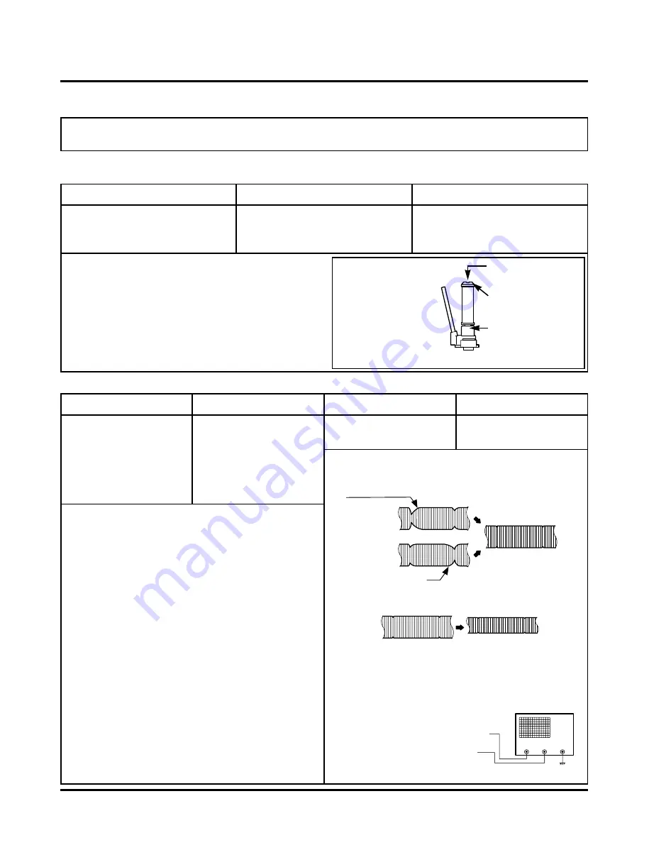
4.Guide Roller Height Adjustment
Adjustment Procedure
1) Confirm that the Tape runs along the Tape Guide Line of the
Lower Drum.
2) If the Tape runs at the Bottom of the Guide Line, turn the
Guide Roller Height Adjustment Screw Clockwise.
3) If it runs at the Top, turn Counterclockwise.
4) Adjust the Height of the Guide Roller to be guided to the
Guide Line of the Lower Drum from the Starting and Ending
Point of the Drum.
Purpose: To regulate the Height of the Tape so that the Bottom of the Tape runs along the
Tape Guide Line on the Lower Drum.
Test Equipment/ Fixture
• Post Height Adjusting Driver
Test Conditions (Mechanism Condition)
• Play or Review Mode
Adjustment Point
• Guide Roller Height Adjustment
screws on the Supply and Take-Up
Guide Rollers.
Fig. C-4-1
Upper Flange
Guide Roller
Retaining Screw
Guide Roller Height
Adjustment screw
ADJUSTMENT DIAGRAM
Test Equipment/Fixture
• Oscilloscope
• Alignment Tape
• Post Height Adjusting
Driver
Test Equipment Connection Points
• CH-1:PB RF Envelope
• CH-2:NTSC: SW 30Hz
PAL: SW 25Hz
• Head Switching Output
Point
• RF Envelope Output
Point
Test Conditions VCR (VCP) State
• Play an Alignment Tape
Adjustment Point
• Guide Roller Height
Adjustment Screws
Fig. C-4-2
Fig. C-4-3
P3 POST
ADJUSTMENT
P2 POST
ADJUSTMENT
Turn the Roller Guide Height
Adjustment Screw slightly
to flatten the waveform.
Tracking control at center
RF ENVELOPE OUTPUT TEST POINT
OSCILLOSCOPE
HEAD SWITCHING OUTPUT TEST
POINT
Turn (Move) the tracking
control to both directions
4-1. Preliminary Adjustment
4-2. Precise Adjustment
Adjustment Procedure
1) Play an Alignment Tape after connecting the Probe of the
Oscilloscope to the RF Envelope Output Test Point and
Head Switching Output Test Point.
2) Tracking Control (in PB Mode): Center Position (When
this Adjustment is performed after the Drum Assembly
has been replaced, set the Tracking Control so that the
RF Output is Maximum).
3) Height Adjustment Screw: Flatten the RF Waveform.
(Fig. C-4-2)
4) Turn (Move) the Tracking Control (in PB Mode)
Clockwise and Counterclockwise. (Fig. C-4-3)
5) Check that any Drop of RF Output is uniform at the
Start and End of the Waveform.
If the adjustment is excessive or insufficient the tape
will jam or fold.
NOTE
Waveform Diagrams
Connection Diagram
Summary of Contents for XBR413
Page 9: ...OVERALL WIRING DIAGRAM 3 2 ...
Page 35: ...3 36 3 37 EE MODE VIDEO TU MODE AUDIO 2 TU IF CIRCUIT DIAGRAM ...
Page 37: ...3 40 3 41 4 JACK CIRCUIT DIAGRAM ...
Page 43: ...3 52 3 53 PRINTED CIRCUIT DIAGRAMS 1 VCR P C BOARD ...
Page 44: ...3 54 3 55 3 TIMER P C BOARD LOCATION GUIDE 2 POWER P C BOARD ...
Page 45: ...3 56 3 57 4 KEY P C BOARD 5 JACK P C BOARD ...
Page 46: ......
Page 59: ...3 70 3 71 CIRCUIT DIAGRAMS 1 E5_BGA POWER UART2 CIRCUIT DIAGRAM ...
Page 60: ...3 72 3 73 2 DDR_SDRAM FLASH CIRCUIT DIAGRAM ...
Page 61: ...3 74 3 75 3 RST CONTROL STATUS_REG ATAPI HOST_CPLD LATCH CIRCUIT DIAGRAM ...
Page 62: ...3 76 3 77 4 1394 ETHERNET_CONNECTOR CIRCUIT DIAGRAM ...
Page 63: ...3 78 3 79 5 VIDEO_IN OUT CIRCUIT DIAGRAM ...
Page 64: ...3 80 3 81 6 AUDIO IN OUT NON STD_VIDEO CIRCUIT DIAGRAM ...
Page 65: ...3 82 3 83 7 AUDIO DAC VIDEO_Y MIXER CIRCUIT DIAGRAM ...
Page 66: ...8 FRONT A V 1934 JACK CIRCUIT DIAGRAM 3 84 3 85 ...
Page 71: ...3 94 3 95 PRINTED CIRCUIT DIAGRAMS 1 MAIN P C BOARD TOP VIEW ...
Page 72: ...3 96 3 97 2 MAIN P C BOARD BOTTOM VIEW ...
Page 102: ...3 127 4 IC302 uPD76f0047 MICOM Pin Assignment ...
Page 124: ......
Page 126: ...3 151 3 152 2 DSP CIRCUIT DIAGRAM No Power No operation DSP IC RESET IC SDRAM R259 0Ω ...
Page 128: ...3 155 3 156 PRINTED CIRCUIT DIAGRAMS 1 MAIN P C BOARD LOCATION GUIDE ...
Page 130: ......
Page 153: ...4 22 GEAR F R GEAR AY P2 P3 F R Lever Tension Base Boss CAM ...
Page 162: ...MEMO ...


