5
Start-Up
(cont.)
4. Start the pump and accelerate to 30 rpm
or to the lowest set point of speed for the
application, whichever is less.
Watch the
point of discharge for evidence of
fluid. If no discharge is seen after 10
revolutions of the shaft shut down the
pump and check for obstructions in
the system and proper pump rotation.
This is assuming a connection can be
broken within a few inches of the
pump outlet port, where the flow would
be evident within several seconds. If
the distance between the pump outlet
and the point of discharge inspection
were long, more time would be needed
before flow is confirmed. This is more
risky, and damage to the pump might
result if it is run dry for more than 30
seconds.
Note:
The pump will discharge a cloud of
bubbles when it is started, but this
will subside when the air is purged
from the pump. This is a normal
part of pump startup.
5.
When smooth flow is seen at the dis-
charge the pump and system can be
gradually brought up to normal oper-
ating speeds and pressure. Listen for
unusual sounds when first starting the
pump and turn the pump off immedi-
ately if any are heard. Investigate for
causes of distress.
6.
If, at any time during operation, the
pump does not appear to be running
smoothly, stop the pump immediately
to avoid serious internal damage.
Flushing of the product piping
Take care when flushing the pump or
downstream process equipment using
the Zenith precision metering pump as
the flushing pump. The pump must be
able to withstand the solvent or flushing
agent as well as the product, and the
operating speed and pressure during
flushing must still fall within the applicable
range for the C-9000 product.
If it is necessary to flush the system,
the following suggestions are recom-
mended to prevent pump damage:
1.
Minimize the differential pressure
across the pump ports to less than
100 psi, but not less than 20 psi.
2.
Reduce the pump speed to an
acceptable level, approximately
50-100 rpm.
3.
Flush the pump for the shortest
allowable time, yielding effective
cleansing of the system, and no
longer than necessary.
4.
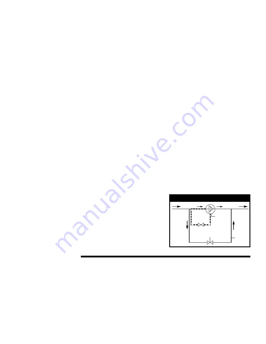
Another alternative is to use a bypass
around the pump, as illustrated in
Figure 2
, this will allow for high velocity
flushing of the downstream system
while minimizing risk to the metering
pump. During the flush cycle, run the
pump slowly. The fluid will pass
through and around the pump. This
will allow the system to be flushed
quickly and effectively.
5.
If it is necessary to also flush the seal
housing, and the discharge pressure
is higher than the suction pressure
(during flushing cycle), connect the
seal housing drain to the suction line
(dotted line on
Figure 2
).
Pump
Valve
Bypass
Figure 2
Care During
Operation
How does the pump work?
Fluid enters the pump through the
inlet port located in the front plate and
fills the gear pocket. As the gears rotate,
a precise amount of fluid is trapped
between the side walls of the gear
pockets and gear teeth.
The metered fluid is transported by the
rotation of the gears to the discharge side
of the pump where the gear teeth come
into mesh. This action forces the fluid out of
the gear teeth and through the outlet port
located in the front plate. The pressure
developed is determined by the pump
size, the gear clearances, pump speed,
fluid viscosity and impedance to flow.
How fast can I run the pump?
Pump speed is limited by practical
considerations. If a high viscosity fluid is
being metered and pump speed is
increased beyond a certain point, the
fluid may not be able to fill the gear teeth
spaces, and the pump will not obtain
enough fluid to maintain normal volumetric


