


Technical modifications excepted. No liability granted for print
ing errors.
© Copyright 2015
· RevA
/ copy deadline: Q4-2015
· English
ZENEC · Bohrturmweg 1 · CH-5330 Bad Zurzach · Schweiz/Switzerland · Mail: [email protected] · www.zenec.com
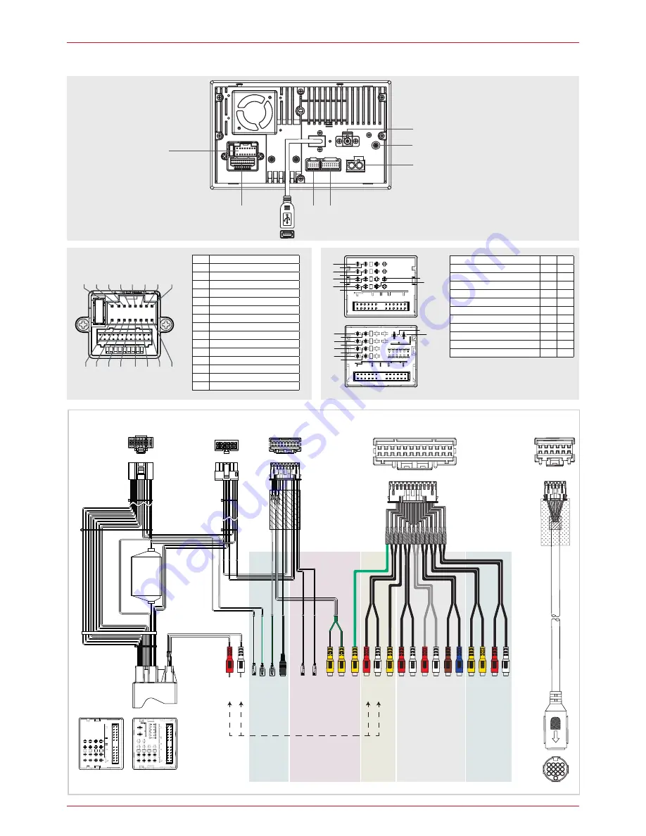
KL 31 / Power GND
B12 C15
KL 30 / Co12V PWR
B15 C16
CAN-Bus
B8
C41
CAN-Bus
B9
C42
Loudspeaker rear right (+)
B1
C1
Loudspeaker front right (+)
B2
C2
Loudspeaker rear right (-)
B5
C5
Loudspeaker front right (-)
B6
C6
Loudspeaker rear left (+)
B4
C4
Loudspeaker front left (+)
B3
C3
Loudspeaker rear left (-)
B8
C8
Loudspeaker front left (-)
B7
C7
A1
KL 31 / Power GND
A2
KL 30 / Co12V PWR
A3
KL 15 /
Sw12V PWR
A4
A5
Sw12V amp PWR*
A6
A7
A8
A9
Loudspeaker rear right (+)
A10 Loudspeaker front right (+)
A11 Loudspeaker rear right (-)
A12 Loudspeaker front right (-)
A13 Loudspeaker rear left (+)
A14 Loudspeaker front left (+)
A15 Loudspeaker rear left (-)
A16 Loudspeaker front left (-)
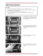
CONNECTION DIAGRAM
A
D
AM/FM
DAB
GPS
E C
A10 A12 A14 A16
A2 A4 A6 A8
A9 A11 A13 A15
A1 A3 A5 A7
A9
Speaker Rear Right (+)
A10 Speaker Front Right (+)
A11 Speaker Rear Right (-)
A12 Speaker Front Right (-)
A13 Speaker Rear Left (+)
A14 Speaker Front Left (+)
A15 Speaker Rear Left (-)
A16
B1
B2
B5
B6
B4
B3
B8
B7
C1
C2
C5
C6
C4
C3
C8
C7
Speaker Front Left (-)
A1
B12
B15
C15
C16
QII QIII
QII QIII
KL 31 / Power GND
A2 KL 30 / Co12V PWR
A3 KL 15 / Sw12V PWR
A4
A5 Sw12V amplifier PWR*
A6
A7
A8 Reverse
Serial No.
EU Legal Representative: ACR S & V GmbH · Industriestr. 35 · D-79787 Lauchringen / Ger
many
*Manufactured under license from Dolby laboratories. "Dolby"
and the double-D symbol are trademarks of Dolby laboratories.
10R-05 1776
R
ev
. A
CLASS 1 LASER PRODUCT
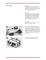
12V DC / 10 A
NEGATIVE
16 PIN CONNECTOR
(DEVICE BACKSIDE)
Remove both loader locking screws BEFORE device installation
FM/AM ANTENNA IN:
SWITCHED 12V SUPPLY
*300mA max current
NAVICEIVER
Z-E2026
QUADLOCK II (
Q
II)
CONNECTORS
QUADLOCK III (
Q
III)
CONNECTORS
B1
B2
B3
B4
B5
B8
C1
C4
C5
C16
C15
C8
B6
B7
C2
C3
C6
C7
B15
B12
Camer
a
B
C
A
F
D
E
Rev
erse*
ex
t. M
ic
Po
w
er max. 300mA
GND
Camer
a A
udio
CVBS I
n*
CVBS I
n*
Line I
n R
Line I
n L
Video I
n
Fr
on
t O
ut R
Fr
on
t O
ut L
Rear O
ut R
Rear O
ut L
SUB (4.2) CNT (5.1)
O
ut
Sub
w
oof
er O
ut
Video O
ut 1
Video O
ut 2
Line O
ut R
Line O
ut L
*eingebaut miteinander verbunden
Line I
n R
Line I
n L
P. CNTR
Rev
erse*
A/V I
n
A/V I
n
Line O
ut
M
-Z
one
Quadlock II
FUSE
Quadlock III
A10 A12 A14 A16
A2 A4 A6 A8
A9 A11 A13 A15
A1 A3 A5 A7
16 PIN CONNECTOR
(DEVICE BACKSIDE)
*
Internally connected
QUADLOCK III (
Q
III)
CONNECTORS
C1
C4
C5
C15
C16
C8
C2
C3
C6
C7
(see note on DAB antenna page 2)


