background image

Clarity Elite 8x8 User Guide, Version 1.5a, 10/2/09

15

Front Panel Commands

IP Address and Baudrate Selection

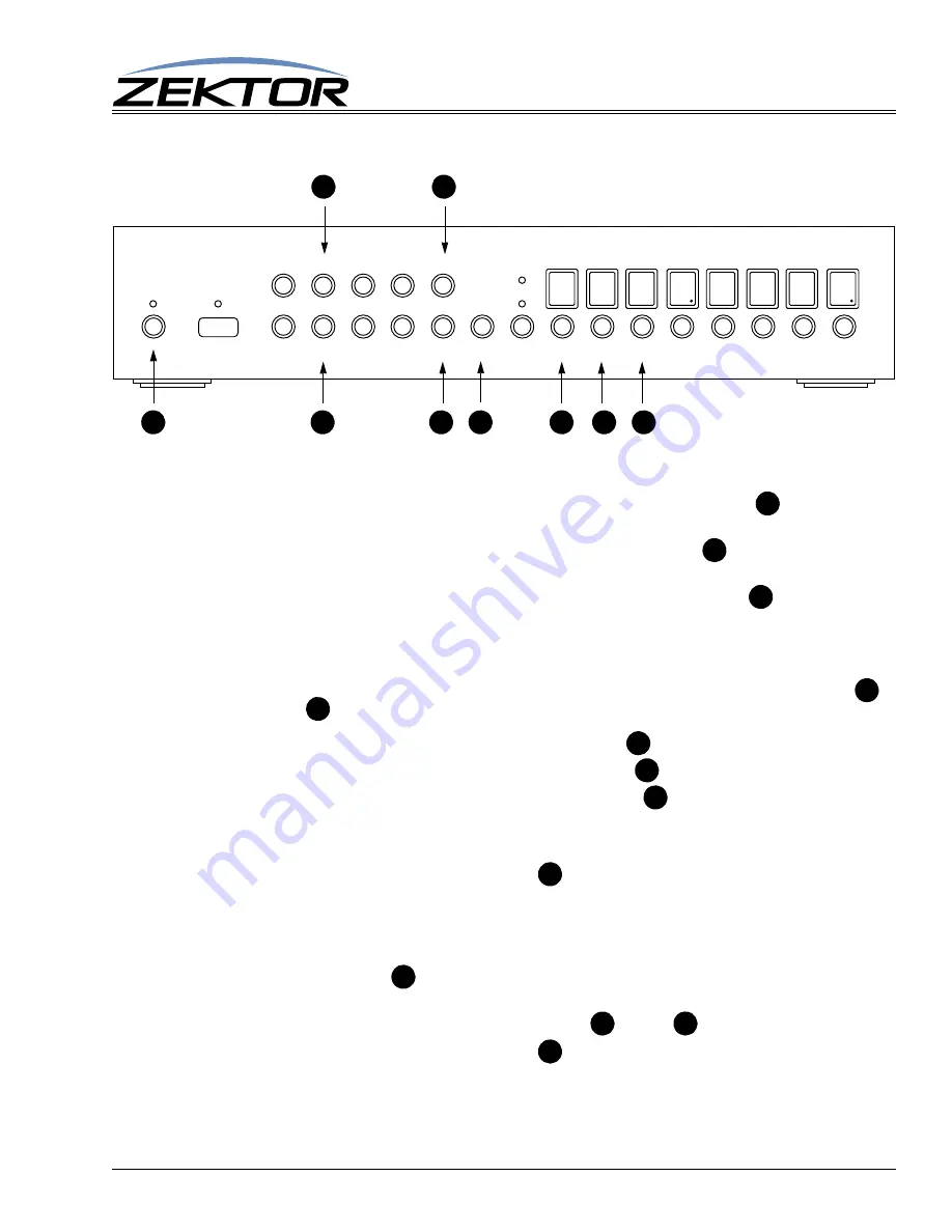
To adjust the IP address:

1

Enter the setup mode to by pressing and releasing the power toggle button 

, the display will 

fill with ‘-’ characters, indicating you are now in the extended setup mode.

To exit the setup mode, at any time, press the power toggle button 

Any changes made will 

be lost!

 The Clarity Elite 8x8 will return to normal operation.

2

Enter the communication setup mode by pressing the in select ‘5’ button 

. The display will 

now show the upper two octets of the IP address.

3

The IP address is made up of four “octets”, the default IP address of the Clarity Elite 8x8 is: 
192.168.001.200.  Each octet is a number between 0 and 255.

To switch between displaying the upper two octets and the lower two octets, use the ‘4’ 


and ‘8’ 

 buttons. Use the zone buttons under each octet to adjust the value:

Any zone button under an octet in the 1’s position 

 will increment the value by 1.

Any zone button under an octet in the 10’s position 

 will increment the value by 10.

Any zone button under an octet in the 100’s position 

 will decrement the value by 1.

Values will wrap around. Incrementing past 255 will cause a value to wrap to 0. Decrementing 
below 0 will cause the number to wrap around to 255.

4

Once set, you must press the ENT button 

 to save the IP address in non-volatile memory.

To change the serial port’s baudrate:

1

Perform above steps 1 and 2. The zone LEDs should now be displaying the upper two octets of 
the IP address.

2

Press the source ‘1’ 

 button, the zone LEDs will now display the current baudrate setting. 

There are two selectable baudrates, 19200 and 9600. The default baudrate is 19200.

3

To switch between the two baudrates, use the ‘4’ 

 and ‘8’ 

 buttons.

4

Once set, you must press the ENT button 

 to save the new baudrate in non-volatile mem-

ory.


AUDIO VIDEO MATRIX SWITCH

AUD

VID

MEM       1          2          3           4

CLR        5          6          7           8       ENT                    1           2          3          4           5          6           7          8

B

A

G

E

H

C

F

I

D

A

A

B

I

C

G

F

E

D

H

I

C

D

Summary of Contents for CLARITY ELITE 8X8

Page 1: ...Component Video Audio Matrix Switch Clarity Elite 8x8...

Page 2: ...2 Clarity Elite 8x8 User Guide Version 1 5a 10 2 09...

Page 3: ...o Video Breakaway 9 Volume Balance Tone Controls and Gains 10 Input Gain Adjustments 11 Composite Converter Controls 12 Using Presets Setup Mode 13 Using Presets Selecting a Preset and Toggling Client...

Page 4: ...4 Clarity Elite 8x8 Serial Protocol Version 1 5a 10 2 09...

Page 5: ...k Start User Guide If anything is missing please get in touch with us as soon as possible so that we can correct the sit uation Features 8x8 active matrix switch with 3 additional composite inputs Ult...

Page 6: ...selection buttons 1 8 Enter button Audio video breakaway selection button Zone selection buttons 1 8 Power indicator IR received Select composite inputs by pressing and holding buttons 1 3 for one sec...

Page 7: ...mposite to component transcoders inputs C O M P O S I T E S V I D E O I N P U T S S P D I F O U T P U T S O P T I C A L I N P U T S WWW ZEKTOR COM SAN DIEGO CA USA V I D E O I N P U T S R Pr B Pb G Y...

Page 8: ...zone or zones have been selected pressing an input button maps the chosen input to the selected zone s By pressing and holding buttons 1 3 the composite to compo nent converters A C and E can be sele...

Page 9: ...one To switch only the video channels of a zone video breakaway 1 Press the audio video breakaway selection button until only the VID LED 2 Following the instructions for Mapping an input to an output...

Page 10: ...abeled you can choose between the different settings The buttons are mapped as Press the 1 button to control Volume 0dB to 100dB range Press and hold the 1 button to control the Master Volume 24dB to...

Page 11: ...now used to switch between inputs not zones 6 There are seperate gain settings for the digital inputs coax and optical and the analog inputs Digital input gains are indicated by a di displayed in the...

Page 12: ...w show the contrast of composite converter A 3 To increase the contrast use the input select button 4 4 To decrease the contrast use the input select button 8 5 By using the buttons labeled you can ch...

Page 13: ...ts decimal point lit this indicates the audio and video settings do not match one of the audio or video settings is turned off while the other is turned on Toggle the the VID AUD LEDs using the VID AU...

Page 14: ...ttons 1 8 are mapped as presets 01 08 Zone buttons 1 8 are mapped as presets 11 18 The ENT button is preset 09 The VID AUD button is preset 10 The MEM button is preset 19 The CLR button is preset 20 A...

Page 15: ...ust the value Any zone button under an octet in the 1 s position will increment the value by 1 Any zone button under an octet in the 10 s position will increment the value by 10 Any zone button under...

Page 16: ...or input 2 Alternatively a composite to component converter can accept s video by using a s video to RCA splitter cable The Y cable of the splitter is connected to the 1 input of a converter and the C...

Page 17: ...puts When present the optical digital audio will be converted to coax digital audio and analog audio The audio will be available as digital audio on the coax outputs and as analog audio outputs Volume...

Page 18: ...y unpleasant crackling and popping type of distortion If you choose to use the tone and equalizer settings of the Clarity Elite 8x8 it is highly recommend that you lower the Master Volume at least 12d...

Page 19: ...M in conversion mode All others in pass through mode Coax input levels 200mV 7 0V PC soundcard compatible Coax output level 500mV nominal 75 Ohms Audio Control Volume range 0dB to 99 5dB in 0 5dB step...

Page 20: ...20 Clarity Elite 8x8 User Guide Version 1 5a 10 2 09 Specifications...

Reviews: