background image

28 - EN

EN - 29

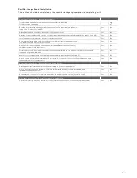
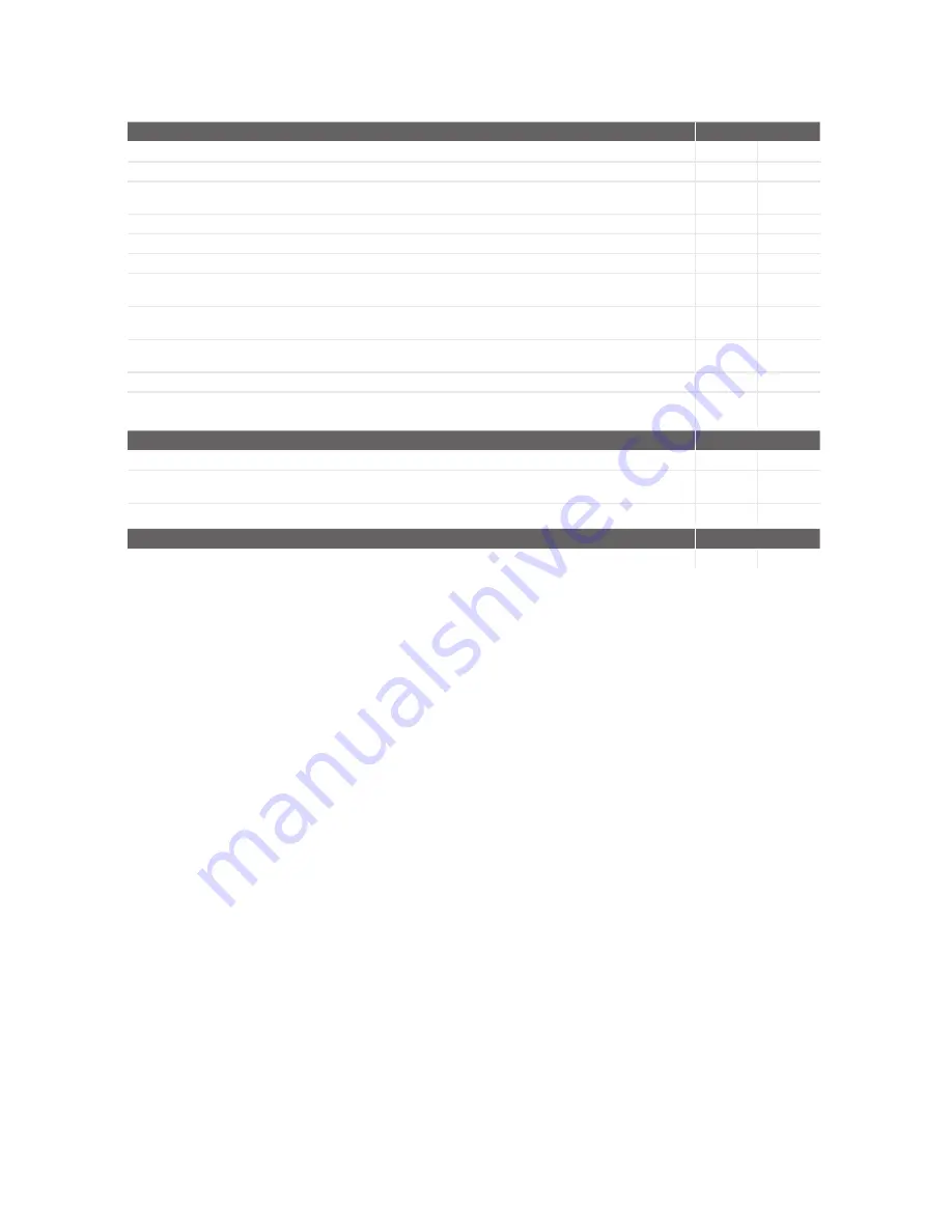
Part 2b - Inspection of installation

This section should be completed by the commissioning engineer prior to completing Part 3.

2.3a Visual inspections - General (all systems)

Total installed equivalent area of background ventilators in dwelling

mm

Total floor area of dwelling

m2

Does the total installed equivalent ventilator area meet the requirements given in 
tables 5.2a, 5.2b, or 5.2c in ADF?

Yes

No

Have all background ventilators been left in the open position?

Yes

No

Have the correct number and location of extract fans/terminals been installed that satisfies table 5.2a in ADF?

Yes

No

Is the installation complete with no obvious defects present?

Yes

No

Do all internal doors have sufficient undercut to allow air transfer between rooms 
(i.e. 10 mm over and above final floor finish)

Yes

No

Has all protection/packaging been removed (including background ventilators) 
such that system is fully functional?

Yes

No

For ducted systems, has the ductwork installation been installed in such manner that air resistance and 
leakage is kept to a minimum?

Yes

No

Are the correct number and size of background ventilators provided that satisfy ADF?

Yes

No

Has the entire system been installed such that there is sufficient access for routine maintenance and 
repair/replacement of components?

Yes

No

2.3a Visual inspections - General (systems 3 and 4 only)

Have appropriate air terminal devices been installed to allow system balance?

Yes

No

Has the heat recovery unit (System 4 only) and all ductwork been effectively insulated where 
installed in unheated spaces?

Yes

No

Condensation connection is complete and drains to an appropriate location (System 4 only)?

Yes

No

2.3c Other inspections - General (systems 1, 3 and 4 only)

Upon initial start up, was any abnormal sound or vibration experiences, or unusual smells detected?

Yes

No

Summary of Contents for ComfoAir Q 350 ST

Page 1: ...Cooling Fresh Air Clean Air Heating Ventilation system Zehnder ComfoAir Q User manual ...

Page 2: ...f this document Use of the unit The unit may only be used when it is properly installed according to the instructions and guidelines in the installer manual of the unit The unit can be used by children aged from 8 years and above persons with reduced physical capabilities persons with reduced sensory capabilities persons with reduced mental capabilities persons with lack of experience and knowledg...

Page 3: ... Set the airflow to a minimum for the period of your absence PRESET A 11 3 1 8 Set the temperature profile 11 3 1 9 Set a schedule 12 3 1 10 Manually set the heat recovery control bypass for a specific duration 12 3 1 11 Stop the ComfoCool Q600 for a specific duration 12 3 2 Menu structure 13 3 2 1 RESET ERROR1 14 3 2 2 TASK MENU 14 3 2 3 STATUS read only 15 3 2 4 FILTERS 16 3 2 5 BASIC OPTIONS 16...

Page 4: ...4 EN ...

Page 5: ... regulations warnings comments and instructions in this document are not obeyed personal injury or damage to the unit can occur After installation all parts that can cause personal injury are secured behind the casing You need tools to open the casing The installation commissioning and maintenance must be carried out by a certified engineer unless the instructions state otherwise A non certified e...

Page 6: ...his is a wired control with a wireless receiver Zehnder ComfoSwitch C 67 For basic remote manual and automatic control of the unit The automatic control is based on the unit settings This is a wired control Zehnder Control App For remote manual and automatic control of the unit with a smartphone or tablet The automatic control is based on the adjustable scheduler This is a controller connected to ...

Page 7: ...ptions Zehnder ComfoConnect KNX C Provide KNX connectivity options Zehnder ComfoConnect LAN C Provide LAN connectivity options for remote control Standby switch Stop the unit remotely This ancillary is connected to the Option Box Error contact Remotely check the error status of the unit This ancillary is connected to the Option Box External filter Filter pollen from the outdoor air Post heater Inc...

Page 8: ...te the unit 2 4 Overview of the display AUTO sensor SHIFT MENU Tu 14 02 A B C E D Position Part A Status indicator LED light B Universal button The function depends on the current text on the display C Up button to Increase fan speed Increase value Select the previous item D Down button to Decrease fan speed Decrease value Select the next item E Universal button The function depends on the current...

Page 9: ... sensor can not overrule the current set airflow G Current ventilation mode AUTO the airflow is set by the scheduler MANUAL the airflow is set by the user H Temporary override of the SCHEDULER VENTILATION I Current fan mode no icon both fans are in operation BALANCE extract fan is not in operation SUPPLY ONLY supply fan is not in operation EXTRACT ONLY both fans are not in operation SERVICE MODE P...

Page 10: ...nt airflow volume in m3 h or l s B Current supply fan mode no icon fan is not in operation fan is in operation C Current outdoor air temperature in C or F Only visible when the supply fan is active D Current supply air temperature C or F Only visible when the supply fan is active E Current extract fan mode no icon fan is not in operation fan is in operation 2 4 3 Overview of the visual signals of ...

Page 11: ...urs the unit will automatically switch back to AUTO mode To set a permanent airflow 1 Navigate to TASK MENU 2 Navigate to AUTO MANUAL 3 Navigate to MANUAL 4 Select the desired airflow with the up and down button 5 Select CONFIRM 6 Select CONFIRM Stop the MANUAL mode 1 Repeat step 1 and 2 2 Navigate to AUTO 3 1 5 Set the airflow to a maximum BOOST for a specific duration 1 Navigate to TASK MENU 2 N...

Page 12: ...th the up and down button 10 Select CONFIRM after each number 11 Select navigate to your desired setting 3 1 10 Manually set the heat recovery control bypass for a specific duration 1 Navigate to TASK MENU 2 Navigate to BYPASS 3 Navigate to OPEN if you would like to minimise the heat recovery control outdoor air is supplied directly into the dwelling DISABLE if you would like to maximise the heat ...

Page 13: ... PROFILE FROST UNBALANCE UNITS2 SCHEDULER FROST PREHEATER3 SEASON DETECTION2 BYPASS POSTHEATER3 RF SETTINGS2 7 COMFOCOOL3 ANALOG INPUT3 SUBSOIL HEAT EXCH 3 COMFOCOOL3 SEASON DETECTION FANS ENERGY INSTALLER DEFAULT2 TASK MENU 1 This menu is only visible when errors occur 2 This menu is only visible when the advanced mode is active 3 This menu is only visible when the accessory is connected to the u...

Page 14: ...ependent in case the installation is equipped with one or more of the options that follow active cooling e g ComfoCool Q600 heating devices e g pre heater and or post heater a regulated subsoil heat exchanger e g ComfoFond L Q SCHEDULER To set the settings automatically based on the set schedule This function is stopped in the permanent MANUAL mode VENTILATION Default PRESET 2 VIEW EDIT view or se...

Page 15: ...subsoil heat exchanger e g ComfoFond L Q STATE view the current state of the regulated subsoil heat exchanger pump OUTDOOR AIR TEMP view the current outdoor air temperature GROUND TEMPERATURE view the current temperature of the regulated subsoil heat exchanger brine liquid COMFOCOOL3 To view the current state of the ComfoCool Q600 STATE view the current ComfoCool Q600 mode and the current ComfoCoo...

Page 16: ...foCool Q600 pre heater post heater ON the unit will increase the airflow in the AUTO mode and MANUAL mode if requested by the built in sensors AUTO ONLY the unit will only increase the airflow in the AUTO mode if requested by the built in sensors OFF the unit will ignore the request to increase the airflow by the built in sensors default setting HUMIDITY COMFORT2 Increase the airflow automatically...

Page 17: ...nd save the current RMOT4 as the heating limit5 COOLING SEASON2 Prevent the unit from counteracting the effect of the central cooling system COOLING LIMIT RMOT4 set the cooling limit6 RMOT4 Default 20 C STARTS NOW start the cooling season and save the current RMOT4 as the cooling limit6 RF SETTINGS2 7 To set the settings of the RF sensor s RF SENSOR PRIORITY2 7 ON the unit will translate the signa...

Page 18: ...nd manufactured for use in balanced ventilation systems incorporating Zehnder heat recovery systems Any other application is seen as inappropriate use and can result in damage to the unit or personal injury for which the manufacturer cannot be held liable The manufacturer is not liable for any damage originating from Non compliance with the safety operating and maintenance instructions in this doc...

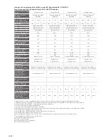
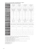
Page 19: ...room controller Warning on the display of the unit or room controller Warning on the display of the unit or room controller Warning on the display of the unit or room controller Internet address for assembly and disassembly instructions www zehnder co uk www zehnder co uk www zehnder co uk www zehnder co uk Airflow sensitivity to pressure variations 10 Indoor outdoor air tightness m h 11 AEC in kW...

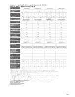
Page 20: ...isplay of the unit or room controller Warning on the display of the unit or room controller Warning on the display of the unit or room controller Warning on the display of the unit or room controller Internet address for assembly and disassembly instructions www zehnder co uk www zehnder co uk www zehnder co uk www zehnder co uk Airflow sensitivity to pressure variations 10 Indoor outdoor air tigh...

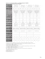
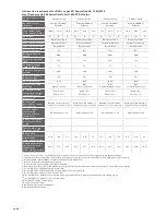
Page 21: ...room controller Warning on the display of the unit or room controller Warning on the display of the unit or room controller Warning on the display of the unit or room controller Internet address for assembly and disassembly instructions www zehnder co uk www zehnder co uk www zehnder co uk www zehnder co uk Airflow sensitivity to pressure variations 10 Indoor outdoor air tightness m h 11 AEC in kW...

Page 22: ...isplay of the unit or room controller Warning on the display of the unit or room controller Warning on the display of the unit or room controller Warning on the display of the unit or room controller Internet address for assembly and disassembly instructions www zehnder co uk www zehnder co uk www zehnder co uk www zehnder co uk Airflow sensitivity to pressure variations 10 Indoor outdoor air tigh...

Page 23: ...troller Warning on the display of the unit or room controller Warning on the display of the unit or room controller Warning on the display of the unit or room controller Internet address for assembly and disassembly instructions www zehnder co uk www zehnder co uk www zehnder co uk www zehnder co uk Airflow sensitivity to pressure variations 10 Indoor outdoor air tightness m h 11 AEC in kWh electr...

Page 24: ...f the unit or room controller Warning on the display of the unit or room controller Warning on the display of the unit or room controller Warning on the display of the unit or room controller Internet address for assembly and disassembly instructions www zehnder co uk www zehnder co uk www zehnder co uk www zehnder co uk Airflow sensitivity to pressure variations 10 Indoor outdoor air tightness m ...

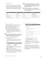
Page 25: ...s more information about the indication on filter replacement Replace the filters at least every six months This will insure a comfortable and healthy air quality and will protect the unit from pollution When you need to replace the filters 1 Order new filters Contact the installer of the unit for providing the correct filters or order online at www epicair co uk Filter set Order number G4 G4 1x 1...

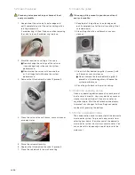
Page 26: ...at least every six months 1 Keep hold of the grille on its outer edge and pull it completely out of the wall or ceiling if not screwed down 2 Clean the grille with a soft brush or vacuum cleaner 3 Clean the filter behind the grille if present with soft brush or vacuum cleaner Do not remove the foam behind the grille if present as it would negatively influence the system performance 4 Place the gri...

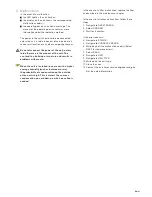
Page 27: ...th mould When the unit is installed in an area with a higher average humidity such as bathroom or wc the probability of condensation on the outside of the unit is high This is almost the same as condensation on a window on which no action is needed In the event of a filter malfunction replace the filter as described in the maintenance chapter In the event of all other malfunctions follow these ste...

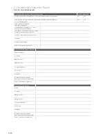
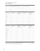
Page 28: ...ese should be detailed here Description of installed controls e g timer central control humidistat PIR etc Location of document override controls Signature Number if applicable Date of Installation completion 2 2 Installation Engineer s Details Engineer s Name Company Address Line 1 Address Line 2 Telephone Number Post Code Signature Competent Person Scheme Registration number if applicable Date o...

Page 29: ... protection packaging been removed including background ventilators such that system is fully functional Yes No For ducted systems has the ductwork installation been installed in such manner that air resistance and leakage is kept to a minimum Yes No Are the correct number and size of background ventilators provided that satisfy ADF Yes No Has the entire system been installed such that there is su...

Page 30: ...e 5 1b in ADF Kitchen Bathroom En Suite Utility Other Other Other 3 4 Air Flow Measurements supply system 4 only Room reference location of terminals Measured Air Flow High Rate l s Design Air Flow High Rate l s Refer to Table 5 1b ADF Measured Air Flow Low Rate l s Design Air Flow Low Rate l s Refer to Table 5 1b in ADF Living Room 1 Living Room 2 Dining Room Bedroom 1 Bedroom 2 Bedroom 3 Bedroom...

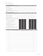
Page 31: ...ctivity Y1 Y2 Y3 Y4 Y5 Y6 Y7 Replace the filters Clean the valves and grilles Clean the operating device Fill the condensation drain of the domestic waste water system Inspect and clean the casing of the unit Inspect and clean the heat exchanger Inspect and clean the fans Inspect and clean the modulating by pass Inspect and clean the pre heater Inspect and clean the condensation drain of the unit ...

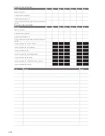
Page 32: ... Y9 Y10 Y11 Y12 Y13 Y14 Replace the filters Clean the valves and grilles Clean the operating device Fill the condensation drain of the domestic waste water system Inspect and clean the casing of the unit Inspect and clean the heat exchanger Inspect and clean the fans Inspect and clean the modulating by pass Inspect and clean the pre heater Inspect and clean the condensation drain of the unit Inspe...

Page 33: ...EN 33 Data Activity Initials ...

Page 34: ......

Page 35: ......

Page 36: ...hnder Group UK Ltd Unit 4 Watchmoor Point Camberley Surrey GU15 3AD T 44 0 01276 605800 F 44 0 1276 605801 info zehnder co uk www zehnderpassivehouse co uk ZGNL_Manual_200502116 V0416 EN Subject to change ...

Reviews: