Zebra Dazzle Manual Download Page 5

Zebra™ Dazzle™ Sump Level Controller

If you have questions or require product support, please call 888.249.4855.

 3

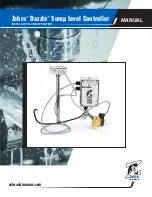
1  Sump Controller Unit

2  Sump Level Sensor

3  Sump Level Sensor low voltage cable

4  Solenoid valve 

5  Solenoid low voltage cable

6  Power cable
 

Mounting the Level Sensor and Solenoid Valve


Mount the Sump Controller unit so that the programming button (shown in Figure 1) is located at the 
bottom of the unit and the unit is level. Screws or bolts can be used to secure the enclosure through 
the mounting holes on the top and bottom flanges.

Mount the Sump Level sensor (item #2 in Figure 2) so the relief holes (Figure 3) are above the sump 
fluid level. Secure the placement to prevent the sensor’s position from changing. Changing the loca-
tion of the sensor after the Sump Controller unit is programmed can result in sump flooding or low 
sump fluid levels. The level sensor must be mounted in the sump at least 1 inch from the bottom of 
the sump. It should always rest in fluids. 

The solenoid valve (item #4 in Figure 2) is a normally closed valve. When the sump requires filling, 
the Sump controller energizes the solenoid coil and opens the valve. Place the solenoid valve in the 
plumbed fill line near the sump.

Figure 2. Sump Controller unit

Figure 3. Sensor Relief holes

Sensor 

relief 

holes

Mount 1” 

from sump 

bottom

Summary of Contents for Dazzle

Page 1: ...If you have questions or require product support please call 888 249 4855 Zebra Dazzle Sump Level Controller SKIMMERS zebraskimmers com INSTALLATION AND OPERATION MANUAL...

Page 2: ...e Sump Level Sensor 4 LEDs when the Sensor is Working Correctly 4 LEDs when the Sensor is Not Working Correctly 4 Sump Level Sensor Wiring 5 Sump Levels 6 LEDs Defined 7 Programming the Sump Controlle...

Page 3: ...nest and good faith to make this manual as comprehensive complete and detailed as possible However all information contained herein is subject to change without notice at the sole discretion of ZSC or...

Page 4: ...ting overflows and putting an end to bucket brigades It is available in sizes to fit all sumps Operating Specifications Power 100 240 Vac 50 60Hz universal transformer Audible alarm 100 dB LEDs 10 red...

Page 5: ...Sump Level sensor item 2 in Figure 2 so the relief holes Figure 3 are above the sump fluid level Secure the placement to prevent the sensor s position from changing Changing the loca tion of the sens...

Page 6: ...rking Correctly When the LEDs flash alternately between yellow and red the sensor is working properly which means that the Sump Level sensor is attached and the Sump Controller unit is ready to be pro...

Page 7: ...Sensor cable item 3 in Figure 2 3 Wire to match the drawing in Figure 6 Be certain to match Yellow Green to the negative connection and Black to the positive connection polarity is critical to the fun...

Page 8: ...fluid in the sump when all machines and attachments that can im pact the sump level are TURNED ON and operating at maximum capacity This is the lowest level that fluids can reach with machines and at...

Page 9: ...LEDs flashing Sump is in emergency alert low condition Solenoid is CLOSED Audible alarm is active Sump is two inches above High level and in emergency alert condition Solenoid is CLOSED Red LEDs flash...

Page 10: ...id level Press and hold the programing button until the unit beeps twice Release the button The LEDs are now in the Set Low Level pattern 3 Place the level of the sump to its minimum level low level w...

Page 11: ...r unit requires immediate attention If the sump level becomes too high or low the following occurs If the level of the sump becomes too high the top 6 LEDs flash red then the top 8 LEDs flash yellow a...

Page 12: ...t side of suggested parameters voids all warranties Pricing and other information subject to change without notice All trademarks of Zebra Skimmers Corporation are listed at Zebra US com All Zebra Ski...

Reviews: