Zebra-Tech D-Opto Operation Manual Download Page 10

Zebra-Tech Ltd


D-OptoLogger Operation Manual


10

The D-Opto Logger will operate correctly until the battery voltage drops below 
around 7.0 volts. If this occurs whilst the D-Opto Logger is in logging mode, the 
last set of data values in the data file will be set to zero, and the D-Opto Logger 
enters a low power sleep mode, with no further data values being logged. 
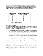
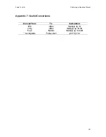


Logging Interval 

(minutes) 

Memory Endurance (Days) 

Standard D-Opto Logger 

1 7 
5 35 

10 70 
15 105 
30 210 
60 420 


Table 1. Memory endurance 


3.4 Routine 

Maintenance 

As with all instruments, it is good operating practice to make regular checks on 
the quality of data being generated by the D-Opto Logger.  This can be carried 
out on site, using one of the following two methods: 
 

1.  Place a recently calibrated transportable dissolved oxygen sensor next to 

the D-Opto Logger and compare the measurements.  It is important to 
allow a sufficient period of time for temperature equilibration to occur.   


2.  Place the D-Opto Logger in a solution of known dissolved oxygen content. 

A solution of 0% dissolved oxygen saturation can be created by adding a 
few teaspoons of sodium sulfite to 1 litre of distilled or fresh tap water.   

 
The D-Opto Logger can tolerate some biofouling, however where possible steps 
should be taken to minimise this; for example covering the D-Opto Logger can 
reduce the amount of bio-growth by restricting available light. . The copper 
biofouling control ring should reduce bio-growth in the area around the optical 
window; this ring is sacrificial and may require replacement on an occasional 
basis. Always use the nylon bolts supplied with the replacement ring to attach the 
ring to the D-Opto Logger, and avoid over tightening.  
 
Periodically it may be necessary to clean the D-Opto optical window, to remove 
bio-growth or other accumulated deposits. 

DO NOT

 use a brush or any object 

that may scratch or damage the optical window. Only use the cleaning pads 
supplied with the D-Opto.  
 

Summary of Contents for D-Opto

Page 1: ...D Opto Logger Dissolved Oxygen Logger Operation Manual...

Page 2: ...9 3 1 Installation 9 3 2 Sealing the D Opto Logger 9 3 3 Logging Endurance 9 3 4 Routine Maintenance 10 3 5 Calibration 11 Appendix 1 Data File Format 13 Appendix 2 Communication Cable Wiring Scheme 1...

Page 3: ...lved oxygen The basic principle involves subjecting a fluorescing compound ruthenium to a fixed wavelength of light When the light source is removed the compound emits a fluorescence the intensity of...

Page 4: ...on of the D OptoLog software During installation the user can select the working path and directory however it is recommended that the default is used c Program Files D OptoLog 2 2 Operation The D Opt...

Page 5: ...the computer s USB port via a USB to serial converter the port number will probably be either com port 4 or 5 The selected com port is maintained in an configuration file on the PC Once the correct p...

Page 6: ...the desired logging parameters The Plot button enables a graphical plot of historic D Opto Logger data to be displayed on the screen The Calibration button opens the D Opto Logger Calibration window F...

Page 7: ...nt of fully aerated water Figure 5 It will accept either altitude m or barometric pressure mBar By pressing the Restore defaults button the original factory calibration values are reinstated by the D...

Page 8: ...Zebra Tech Ltd D OptoLogger Operation Manual 8 Figure 5 Pressure Correction Calculator...

Page 9: ...ced prior underwater deployment 1 Using the O ring pick supplied remove the O rings from the inside of the end cap and the body of the D Opto Logger 2 Using a lint free tissue clean the O ring seats t...

Page 10: ...to allow a sufficient period of time for temperature equilibration to occur 2 Place the D Opto Logger in a solution of known dissolved oxygen content A solution of 0 dissolved oxygen saturation can be...

Page 11: ...1 Place the D Opto Logger in the reference solution and allow equilibrating for at least 30 minutes 2 Power up the D Opto Logger and start D OptoLog Once the measurements have stabilised press the Cal...

Page 12: ...minutes 2 Power up the D Opto Logger and start D OptoLog Once the measurements have stabilised press the Calibrate button in the main window to open the Calibration window 3 Enter the pressure correct...

Page 13: ...ptoLogger Operation Manual 13 Appendix 1 Data File Format Data Field Number Description 1 Year 2 Month 3 Day 4 Hour 5 Minute 6 Second 7 Battery voltage 8 Temperature Degrees C 9 Dissolved Oxygen 10 Di...

Page 14: ...Zebra Tech Ltd D OptoLogger Operation Manual 14 Appendix 2 Communication Cable Wiring Scheme...

Page 15: ...battery and communication socket there is an LED The LED flashes according to the current status of the D OptoLogger The interval between the flashing sequence may be up to 8 seconds 1 Flash Operation...

Page 16: ...e instrument has been carefully designed to prevent electrical interference impacting on the operation Under extreme conditions however noise may become a problem Track down the source of noise this c...

Page 17: ...ter Resolution Temperature 00 01 Deg C DO saturation 000 01 PPM 00 001 ppm Sensor Drift 1 per year provided measurement interval 10 minutes Power supply 1 x PP9 9 volt alkaline battery Duracell or Ene...

Page 18: ...1 983 97 343 1126 973 96 431 1413 963 95 519 1703 952 94 608 1995 942 93 698 2290 932 92 789 2587 922 91 880 2887 912 90 972 3190 902 89 1066 3496 899 88 1160 3804 882 87 1254 4115 871 86 1350 4430 86...

Page 19: ...Ltd D OptoLogger Operation Manual 19 Appendix 7 Useful Conversions Convert from To Calculation kPA mBar Multiply by 10 inHg mBar Multiply by 33 85 Feet Meters Multiply by 0 3048 Centigrade Fahrenheit...

Page 20: ...Zebra Tech Ltd D OptoLogger Operation Manual 20 Zebra Tech Ltd Contact Details PO Box 1668 Nelson New Zealand Tel 0064 03 5471590 Fax 0064 03 5471598 Email enquiry zebra tech co nz...

Reviews: