background image

Page 39

8 PERIODIC MAINTENANCE TO BE REPEATED

AT TIMES INDICATED

Check the wear and condition of the Contactors’ moving and fixed contacts.
Electrical Contacts should be checked every 

3 months.

Check the Foot pedal or Tiller microswitch.  Using a suitable test meter, confirm that
there is no electrical resistance between the contacts by measuring the volt drop
between the terminals.  Switches should operate with a firm click sound.
Microswitches should be checked every 

3 months.

Check the Battery cables, cables to the chopper, and cables to the motor.  Ensure the
insulation is sound and the connections are tight.
Cables should be checked every 

3 months.

Check the mechanical operation of the pedal or tiller .  Are the return springs ok.  Do
the potentiometers wind up to their full or programmed level.
Check every 

3 months.

Check the mechanical operation of  the Contactor(s).  Moving contacts should be free
to move without restriction.
Check every 

3 months.

Checks should be carried out by  qualified personnel and any replacement  parts used
should be original.  Beware of NON ORIGINAL PARTS.
The installation of this electronic controller should be made according to the diagrams
included in this Manual.  Any variations or special requirements should be made after
consulting a Zapi Agent.  The supplier is not responsible for any problem that arises
from wiring methods that differ from information included in this Manual.

During periodic checks,  if a technician finds any situation that could cause damage or
compromise safety,  the matter should be bought to the attention of a Zapi Agent
immediately.  The Agent will then take the decision regarding operational safety of the
machine.

Remember that Battery Powered Machines feel no pain.

NEVER USE A VEHICLE WITH A FAULTY ELECTRONIC CONTROLLER.

Summary of Contents for Chopper SEM-X

Page 1: ...INSTALLATION AND USER MANUAL CHOPPER SEM X ELECTRONIC INDUSTRIAL DEVICES 42028 POVIGLIO R E Via Parma 59 ITALIA Tel 39 0522 960050 r a Fax 39 0522 960259 e mail zapi zapispa it...

Page 2: ...ts via Console 15 4 2 Description of Console Connection 15 4 3 Description of Standard Console Menu 16 5 SEM X Cabling and Configuration 17 5 1 Power Diagram 17 5 2 Description of Programmable Functio...

Page 3: ...Y N A P M O C S E C I V R E S T P E D Y N A P M O C E V I T U C E X E T N E M E G A N A M E V I T U C E X E T N E M E G A N A M E V I T U C E X E T N E M E G A N A M E V I T U C E X E T N E M E G A N...

Page 4: ...actor NPC Negative Pump Contactor NPOT Negative Potentiometer PC Pump Contactor PEMB Positive Electromechanical Brake PEV Positive Lowering Valve PHORN Positive Horn PMC Positive Main Contactor PPC Po...

Page 5: ...e end user Various chopper configurations can be selected by the user without the need for hardware modifications Future technological updates are made easy for the user The communication protocol wil...

Page 6: ...C VERSIONS MAXIMUM CURRENT VOLTAGE DROP IN FULL CONDUCTION 24V 90A 3 0 14V at 35A 25 C 24V 110A 2 0 14V at 35A 25 C 2 2 CONTROL UNITS 2 2 a Microswitches Microswitches should have a contact resistanc...

Page 7: ...on in either direction This function is unique when it is necessary to compensate for asymmetry with the mechanical elements associated with the potentiometer especially relating to the minimum level...

Page 8: ...eration cannot commence if these operations are not carried out correctly Requests for drive must be made after closing the key Switch Protection against uncontrolled movements The Line Contactor will...

Page 9: ...f the motor is rotating the chopper controls the speed and automatically brakes and keeps the motor at a very low speed during descent on a gradient This is a very useful safety feature and is not dri...

Page 10: ...ure Battery Voltage Diagnosis is provided in 3 ways The Red Led connected to Connector B will flash a certain number of times for a given Alarm See Listings or the Digital Console may be used or MDI A...

Page 11: ...a traction battery Do not use the outputs of converters or power supplies For special applications please contact the nearest Zapi service centre Start the machine the first time with the drive wheel...

Page 12: ...connections to the motor armature and battery use cable of 10mm section For the Field connections use cable of 4mm section For the optimum chopper performance the cables to the battery should be run s...

Page 13: ...wire input A3 PPOT Provides a positive to supply accelerator s potentiometer protected against short to B and B A4 TILLER Tiller seat microswitch input active high B A5 BELLY Belly switch input used f...

Page 14: ...ected against shortcircuit A15 PMC Line contactor coil positive supply 1 0A continuous A16 KEY Controller supply must be connected to B through a cable and a 6 3A fuse PIN REFERENCE B1 B2 NCLRXD B3 PC...

Page 15: ...Page 14 3 6 MECHANICAL DRAWING DIMENSIONS...

Page 16: ...ade using the Digital Console The Console is connected to the B connector of the SEM X Chopper Pay attention to the polarity of the Console Connector when connecting to the chopper The bevel on the co...

Page 17: ...Page 16 4 3 DESCRIPTION OF STANDARD CONSOLE MENU...

Page 18: ...Page 17 5 SEM X CABLING AND CONFIGURATION 5 1 POWER DIAGRAM...

Page 19: ...2 5 PRESENT A11 output drives an electromechanical brake The controller does not carry out monitor function but locks the brake while in rest or alarm status 4 BATTERY CHECK ON alarm indication speed...

Page 20: ...f the menu appears on the Display 8 Press either ROLL UP or ROLL DOWN to bring up the next the Option 9 A new Option appears on the Display 10 When the desired Option is displayed press PARAM Top Righ...

Page 21: ...irst speed reduction active when H S is active 6 CUTBACK SPEED 2 Second speed reduction active when DIGITAL INPUT2 is active 7 MAX SPEED FORW Maximum Forward Speed obtained by weakening the Field Curr...

Page 22: ...Nominal Field Current 15 CREEP SPEED Minimum Speed This Parameter sets the minimum voltage applied to the motor at the start of travel 16 FIELD CURR MAX Maximum field current The chopper reaches this...

Page 23: ...92 84 77 70 63 56 48 42 38 MAX SP BACK FINE FCN 0 1 2 3 4 5 6 7 8 9 TRACTION I MAX IMax 72 76 79 81 84 86 90 94 96 100 ARMA CUR NOM ACN IMax 29 31 34 36 39 41 44 46 49 51 WEAK DROP OUT ACN 30 35 40 45...

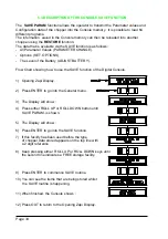
Page 24: ...he names of the Parameters appear on the Display 8 When the desired Parameter appears the Display will show a Level Number that will be between 0 and 9 press either PARAM Top Right or SET Bottom Right...

Page 25: ...tester menu 2 SET FLD CURRENT Field current maximum value used to calibrate field current displayed in tester menu 3 ADJUSTMENT 01 Adjustment of the 90 threshold of the battery discharge table 4 ADJUS...

Page 26: ...5 7 MENU ADJUSMENT 1 ADJUST BATTERY Sets the correct battery voltage level 2 THROTTLE 0 ZONE Sets the pedal curve type 3 THROTTLE X POINT Sets the pedal curve type 4 THROTTLE Y POINT Sets the pedal cu...

Page 27: ...Page 26 5 8 SEM X TRACTION STANDARD WIRING DIAGRAMS...

Page 28: ...er 5 5 6 Set the Acceleration Delay requirements for the machine Test the parameters in both directions 7 Set the CREEP level starting from level 0 The machine should just move when the accelerator mi...

Page 29: ...K 5 NO FIELD CURR Field wiring not OK or field current sensor not OK 5 FW HIGH FIELD CUR Field wiring not OK or field current sensor not OK in FWD direction 5 BW HIGH FIELD CURR Field wiring not OK or...

Page 30: ...or failed b Error in the starting sequence from the operator c Error in the wiring 5 FORW BACK AL 80 MDI This check is made continually The alarm is generated when forward and reverse direction are re...

Page 31: ...fault is detected NPOT or PPOT are open circuit 11 FWD HIGH FIELD CURR AL 90 MDI BWD HIGH FIELD CURR AL 91 MDI NO FIELD CURR AL 58 MDI Problem detected with the field winding current Possible causes a...

Page 32: ...ase in temperature At 90 C the chopper totally stops If the temperature of the chopper is 10 C this Alarm is also generated and the current is reduced by 80 If this alarm is displayed when the chopper...

Page 33: ...7 FORWARD SWITCH the level of the Forward direction digital entry MA pin B6 ON VB active entry of closed switch OFF GND non active entry of open switch 8 BACKWARD SWITCH the level of the Reverse direc...

Page 34: ...to the TESTER function 7 The first variable to be tested is shown on the Display 8 Press either ROLL UP or ROLL DOWN buttons until your desired variable for measurement appears on the Display 9 Next v...

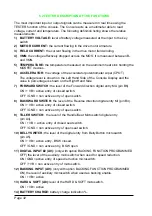
Page 35: ...showing how to use the SAVE function of the Digital Console 1 Opening Zapi Display 2 Press ENTER to go into the General menu 3 The Display will show 4 Press either ROLL UP or ROLL DOWN button until S...

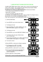
Page 36: ...he Digital Console 1 Opening Zapi Display 2 Press ENTER to go into the General menu 3 The Display will show 4 Press either ROLL UP or ROLL DOWN button until RESTORE PARAM appears on the display 5 The...

Page 37: ...ening Zapi Display 2 Press ENTER to go into the General menu 3 The Display will show 4 Press ROLL UP or ROLL DOWN button until PARAMETER CHANGE appears on the display 5 The Display will show 6 Press E...

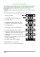
Page 38: ...on until PROGRAM VACC appears on the display 5 The Display will show 6 Press ENTER to go into the PROGRAM VACC routine 7 The Display will show the minimum and maximum values of potentiometer wiper out...

Page 39: ...X Part Number Description C16519 Protected 150A Fuse C16503 Protected 200A Fuse C16520 6 3A 5x20mm Control Circuit Fuse C12404 16 Way Molex Minifit Connector C12777 Insert for Molex Minifit Connectors...

Page 40: ...level Check every 3 months Check the mechanical operation of the Contactor s Moving contacts should be free to move without restriction Check every 3 months Checks should be carried out by qualified p...

Reviews: